
Review the stainless steel junction box
Review the listed 4-in/1-out configuration and product images, then confirm sensor count, wiring, trimming method, cable entry and enclosure requirements.
Open product pageWhat a useful accessory enquiry should resolve
Select a load cell junction box, floor scale accessories or replacement components from the existing weighing system—not from appearance alone. FMSCales reviews the sensor model, load path, wiring, enclosure, indicator, installation conditions and required quantity before confirming a compatible quotation route.
This range helps weighing-equipment manufacturers, industrial scale dealers, maintenance teams, service partners and system integrators identify a compatible junction box, mounting component or floor-scale kit for an existing or planned scale. Start with the installed equipment and service task, then review product-specific wiring, enclosure, capacity-option and included-component details before quotation.
A similar enclosure, connector or mounting part is not proof of interchangeability. The quoted scope must match the identified sensors, mechanical assembly, signal route and intended verification procedure.
Load Cell Accessories: Open a product page for model-specific specifications, images and configuration details.
Review the listed 4-in/1-out configuration and product images, then confirm sensor count, wiring, trimming method, cable entry and enclosure requirements.
Open product pageReview the listed load-cell, junction-box, indicator, cable and mounting scope before matching capacity, platform geometry and interface details.
Open product pageSeparate mechanical binding, damaged wiring, moisture, junction-box faults, sensor problems and indicator settings before ordering a replacement component.
Open product pageReview load direction, mounting architecture, capacity, environment, cabling and acceptance evidence when the accessory request is part of a wider sensor change.
Open product page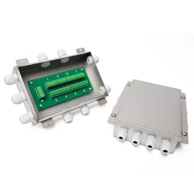 View product details
Stainless Steel Load Cell Junction Box for Industrial Weighing Systems.
 View product details
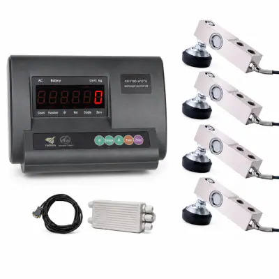
Floor Scale Accessories Kit with Load Cells, Junction Box, Indicator and Data Cable.
The two current product options address different procurement scopes. Start with what is being repaired or built, then confirm every mechanical and electrical interface.
| Product route | Current listed scope / Useful starting point | Confirm before quotation |
|---|---|---|
| Stainless steel load cell junction box | A multi-load-cell signal connection enclosure with a listed 4-in/1-out configuration. A scale whose sensor count, wiring and instrument route are already known. | Load-cell quantity and output, wiring, trimming, cable glands, enclosure environment, dimensions and indicator connection. |
| Floor scale accessories kit | A kit option that includes load cells, junction box, indicator, data cable and mounting accessories. A floor or platform scale build, refurbishment or matched-component replacement. | Platform, load entry, total capacity, sensor arrangement, mounts, cable length, display, power, data and installation responsibility. |
Compare labels, drawings, bolt pattern, force direction, movement and cable arrangement against the existing assembly. This gives the buyer and service team a traceable compatibility decision before shipment.
Check the receptor, mounts, cable, junction box, excitation, signal and indicator in a safe diagnostic order. The replacement scope is based on the observed fault route instead of an unverified assumption.
Freeze the required sensors, mounts, junction box, cable, indicator, connectors, documentation and installation responsibility. Procurement can compare a complete bill of material rather than isolated component prices.
Plan inspection, corner checks, calibration and verification after mechanical or electrical work is completed. The handover includes a defined route back to service instead of ending at component installation.
A product label and several clear installation photographs are often more useful than a generic request for “the same part.” Send what is available; unknown fields can be identified during technical follow-up.
Collect labels, product references, drawings, wiring information and photographs without disconnecting equipment unsafely.
Confirm whether the requirement is a junction box, mounting hardware, cable, indicator, sensor set or complete floor-scale kit.
Match mechanical dimensions, sensor count, signal route, enclosure, documentation, spares and repeat-order needs.
Freeze the supplied components, exclusions, installation party, checks, packing, destination and document revision.
Complete competent installation, inspect the load path and wiring, then perform the agreed functional and calibration checks.
The application explains the surrounding system; it does not make an unverified component interchangeable with the installed hardware.
Coordinate sensors, mounts, junction box, cabling and indicator around platform dimensions, load entry and the intended weighing task.
Review the applicationReview multi-cell connections, cable protection, access, grounding and return-to-service checks for the identified weighbridge.
Review the applicationMatch load direction, vessel movement, piping forces, mount geometry, junction arrangement and process-control interface.
Review the applicationControl drawings, interfaces, labels, component revisions and repeat-order records for a defined equipment programme.
Review the applicationIdentify the actual fault, plan safe replacement and retain the component and verification record for future service.
Review the applicationThe required checks depend on the scale, component changed, intended use and local obligations. A component label or bench reading alone does not establish complete-system performance or approval.
FMSCales supports load cell accessories enquiries through product identification, component matching, document coordination, quotation review and follow-up for the selected industrial weighing system. The technical discussion starts from the existing assembly and required service outcome.

Our production environment supports fabrication, assembly and project preparation for selected industrial weighing equipment and system configurations.

Model-specific inspection, functional checks and calibration preparation help align the selected equipment, documentation and project requirements before delivery.
Request current documents for the exact product, revision and identified weighing system. Availability and application scope should be confirmed before installation.
Stainless Steel Load Cell Junction Box for Industrial Weighing Systems.
Floor Scale Accessories Kit with Load Cells, Junction Box, Indicator and Data Cable.
Selection and application guides
Selection and application guides
Selection and application guides
Selection and application guides
Distributors, scale builders and service companies can discuss matched components for repairs, stock planning, OEM builds and repeat projects. Send the installed-system information and intended service scope so the response addresses a real bill of material.
Provide the number and model of load cells, signal and wiring information, current junction-box label, indicator model, cable entries and installation photographs. The enclosure and terminal count must match the actual system; appearance alone is not enough to confirm compatibility.
No universal fit should be assumed. Confirm sensor quantity, output, excitation, wiring, trimming method, terminal arrangement, shielding, enclosure and the instrument connection before selecting the junction box.
The current kit option includes load cells, a junction box, weighing indicator, data cable and mounting accessories. The exact capacity, quantities, interfaces, cable lengths, documents and installation scope must be confirmed in the quotation.
Not before checking the complete system. Mechanical binding, damaged cable, moisture, poor connections, junction-box faults, power, grounding or indicator settings can produce similar symptoms. Follow a safe diagnostic sequence before defining the replacement part.
Share the load-cell model, capacity, force direction, mounting dimensions, vessel or platform movement, restraint, overload protection, environment and drawings. Mechanical compatibility is part of the complete load path, not only the bolt pattern.
Inspect the mechanical assembly and wiring, confirm instrument response, then complete the applicable zero, corner, calibration and functional checks. The exact return-to-service procedure depends on the scale, changed component and intended use.
Channel partners can discuss repeat-supply, packaging and private-label requirements for an identified component set. Confirm drawings, interfaces, labels, quantity, revision control, destination and after-sales responsibilities before the supply programme is agreed.
Include the scale and load-cell models, sensor quantity, junction box or indicator, required part, dimensions, wiring, environment, observed issue, quantity and destination country.
Send the available labels, photographs and system details so the first response can focus on compatibility and supply scope.
Send your core application details. We will review the request and follow up by email or Tel / WhatsApp.