Choosing a load cell is not a catalogue exercise. The correct starting point is the load path: what carries the load, where the force enters the structure, how it reaches the sensor, and which forces must be allowed to move without corrupting the measurement. Only after that review should a buyer compare capacity, sensitivity, accuracy class, material, sealing, cable, and certificate details.
That order matters because a highly specified sensor can perform poorly in a badly designed structure, while a suitable sensor with the right mounting hardware can give repeatable service without being the most expensive item on the shortlist. The load cell, mounting assembly, junction box, indicator, structure, cabling, calibration method, and operating procedure form one measuring system. Procurement should therefore approve them as a system rather than treating the load cell as an interchangeable spare part.
This guide is for industrial scales used for internal control, batching, inventory, vehicle weighing, platform weighing, vessels, and related applications. It does not certify any FMSCales model for a particular project. If the result will determine a commercial transaction, tax, enforcement action, or regulated declaration, the buyer must confirm the complete instrument approval and local verification requirements for the intended market.
Begin with the weighing task, not the sensor shape
A useful load-cell enquiry begins with a short description of the decision that follows the weight. A warehouse floor scale may release a pallet to dispatch. A hopper scale may stop a feeder. A truck scale may create a gross, tare, and net transaction. A tension system may monitor a suspended load. These tasks produce different requirements for loading direction, stability, update behaviour, traceability, access, and legal control.
Write down the following before choosing a sensor family:
- the load receptor and supporting structure;
- the normal load, minimum useful load, and worst credible load;
- whether the load is centred, moving, suspended, eccentric, or applied through piping;
- the number of support points and whether all supports will be instrumented;
- static, cyclic, impact, vibration, wind, thermal, and side-load conditions;
- the required displayed increment and the business decision based on it;
- the installation environment and cleaning method;
- the planned indicator, junction box, cable route, and communication path;
- the reference standard and acceptance method;
- whether the system is for internal process use or a regulated legal-for-trade function.
This information exposes conflicts early. For example, a vessel may need freedom to expand as temperature changes, yet connected pipework can pull it sideways. A platform may be designed for centred test weights but used by pallet trucks that enter at the corner. A truck scale may have adequate total capacity while individual supports experience very different loads during braking or off-centre entry. A capacity number alone does not resolve any of these conditions.
Match the sensor architecture to the load path
Load-cell names vary among manufacturers, but several architectures appear repeatedly in industrial weighing. The right choice depends on how force enters the sensor and how the surrounding structure controls unwanted movement.
| Architecture | Common weighing role | Buyer should examine | Frequent design mistake |
|---|---|---|---|
| Single-point | Bench and smaller platform scales | Approved platform size, eccentric-load behaviour, mounting surfaces, cable protection | Assuming any platform size can be fitted because the total load is within capacity |
| Bending or shear beam | Floor scales, hoppers, small vessels, conveyors | Load introduction, mounting kit, lateral restraint, moisture path, service access | Bolting the beam between surfaces that are not flat or aligned |
| Double-ended shear beam | Vehicle scales and larger vessels | Rocker or link arrangement, bridge movement, end restraint, lightning and surge protection | Replacing only the sensor without checking the mating hardware and orientation |
| Compression or canister | High-capacity platforms, tanks, test systems | Alignment, anti-rotation, lift-off control, foundation stiffness, side-force control | Applying a nominally vertical load through an unstable or binding interface |
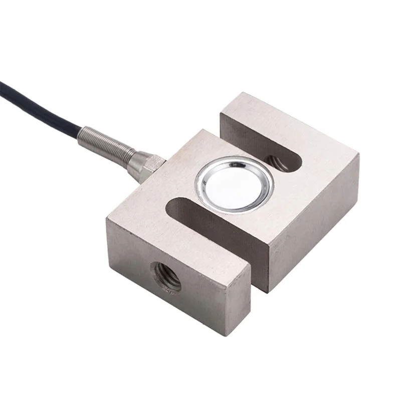
| S-type or tension/compression | Suspended hoppers, hanging scales, force monitoring | Thread alignment, rod ends, anti-rotation, tension safety, compression buckling | Allowing the cable or structure to twist the sensor |
| Load pin or specialised sensor | Sheaves, shackles, pivots, machinery | Pin geometry, bearing pattern, orientation, retention, fatigue and machine safety | Treating a purpose-designed machine element as a drop-in generic load cell |
This table is a screening tool, not a substitute for the load-cell manufacturer's drawings and installation instructions. Two sensors with the same architecture and rated capacity may require different mounting clearances, load buttons, torque, cable entry, and overload protection. Procurement should request the drawing and mounting instructions before the structure is frozen.
Capacity selection requires an engineering load case
The rated load of a scale is not automatically the required capacity of each sensor. The design team must translate the complete structure into forces at each support. That calculation should include dead load, useful load, load distribution, centre-of-gravity movement, impact, temporary overload, uplift, side force, and the effect of uneven foundations or structural deflection.
For a four-cell platform, dividing maximum scale capacity by four gives only an idealised average. It does not describe a forklift placing a pallet near one corner, a truck wheel crossing a module joint, a vessel filled unevenly, or a foundation that settles. Likewise, selecting a very large load cell "for safety" can work against the desired measuring range if the operating load uses only a small portion of the sensor's range. The correct margin is project-specific and should be justified by structural and metrological review rather than a universal safety-factor slogan.
Ask the supplier to identify four separate values and their conditions:
- Rated capacity: the load range over which the stated performance applies.
- Safe overload: a manufacturer-defined limit that should not cause a specified permanent performance change under the stated conditions; it is not a normal operating target.
- Ultimate overload: a different limit associated with structural failure risk; it is not a working allowance and must not replace machine or structure safety design.
- Minimum useful signal or measuring range: the lower end at which the complete system can meet the intended indication and acceptance requirement.
These values must be read from the exact model documentation. Terms are not always used identically across vendors, and none of them removes the need for mechanical stops, lift-off protection, traffic control, or other safeguards where the application requires them.
Read the data sheet as a system document
A load-cell data sheet contains several performance terms that are easy to compare incorrectly. The most familiar number is rated output, often expressed as millivolts per volt. It describes a nominal electrical output relative to excitation at rated load. It does not by itself state the accuracy of the completed scale.
The buyer should also review:
- non-linearity, hysteresis, and repeatability definitions;
- creep and creep recovery over the stated time;
- zero balance and temperature effect on zero;
- temperature effect on sensitivity;
- compensated and operating temperature ranges;
- input and output resistance or impedance;
- insulation resistance;
- excitation limits;
- cable length, construction, and whether cable trimming is permitted;
- environmental protection and construction material;
- accuracy class, maximum number of verification intervals, and minimum dead-load output return where applicable;
- the exact test conditions and whether values are typical, maximum, or guaranteed.
Do not add values from unrelated conditions. A "combined error" from one supplier may not contain the same components or use the same test sequence as a value from another. A laboratory performance specification also does not account for platform deflection, pipe forces, corner loading, junction-box adjustment, indicator noise, or site temperature gradients.
OIML R 60-1:2021 defines metrological and technical requirements for load cells, while R 60-2:2021 addresses metrological controls and performance tests. Its classification and test language gives procurement a disciplined way to examine load-cell documentation. It does not mean that any load cell mentioning OIML R 60 is approved for every complete scale, market, or application. The exact certificate, model designation, variant, load transmission, cable, and conditions must be checked.
Mechanical installation often decides the result
Many apparent sensor problems begin outside the sensor. A load cell is intended to respond to a defined force direction. Side loads, bending moments, torsion, binding, poor alignment, debris, and thermal restraint create additional forces that the calibration did not represent.
Mounting assemblies are therefore functional parts of the measurement. Depending on the system, they may introduce load through a rocker, ball, cup, bearing, rod end, plate, or elastomer. They may also control lateral movement, uplift, rotation, and service replacement. Replacing a purpose-designed mounting assembly with a fabricated stack of plates can change both the load path and the safety behaviour.
During design review, check:
- support surfaces are flat, stiff, and capable of carrying the local load;
- mounting-hole position and bolt grade follow the exact drawing;
- the loading point remains aligned through the intended movement range;
- check rods, bumpers, and restraints do not bind during normal movement;
- vessels can expand without transferring pipe or thermal force into the measurement;
- cables have strain relief and protection from crushing, rodents, welding current, chemicals, and standing water;
- lift-off, tipping, wind, impact, and vehicle forces are managed by the structure, not assumed to be absorbed by the sensor;
- the cell can be inspected and replaced without creating an unsafe lifting operation.
The acceptance plan should include an off-centre or corner response test where the scale design and applicable requirements call for one. If a platform gives different results by load position, adjusting the junction box may mask only part of the problem. The team should first inspect foundation level, platform freedom, mounts, restraints, load introduction, cable integrity, and repeatability.
Environment is more than an IP code
An enclosure rating can help compare protection against specified ingress conditions, but it cannot describe every industrial environment. Continuous submersion, pressure washing, condensation, salt, fertiliser, corrosive chemicals, temperature cycling, abrasive dust, and cable damage are different failure mechanisms.
For outdoor or washdown service, review the complete path from sensing element to junction box. A stainless-steel body does not guarantee that cable entry, connector, mounting hardware, junction box, fasteners, and surrounding structure have equivalent resistance. A hermetically sealed construction and a potted construction are not automatically interchangeable. Ask what sealing method applies to the quoted model and how repairs or cable changes affect it.
Temperature deserves the same care. The compensated range describes the range over which specified temperature-related performance applies; the operating range may be broader but with different performance expectations. A scale exposed to sun on one side, refrigerated washdown, hot product, or rapid day-night changes may experience gradients that a uniform laboratory temperature test does not reproduce. The project should define warm-up, zero checking, calibration verification, and shutdown limits around the actual process.
Hazardous locations require a separate protection review. A general statement such as "explosion-proof load cell" is not enough. The buyer must check the complete equipment certificate, protection concept, gas or dust group, temperature class, equipment protection level or zone/division, barriers, cabling, junction boxes, indicator location, and installation rules for the jurisdiction. No generic article can approve that configuration.
Confirm electrical compatibility before ordering
The signal chain begins at the load-cell bridge and ends at the value used by the operator or control system. Check every interface in between.
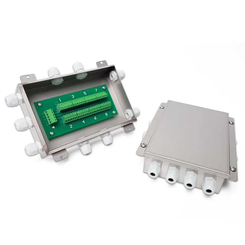
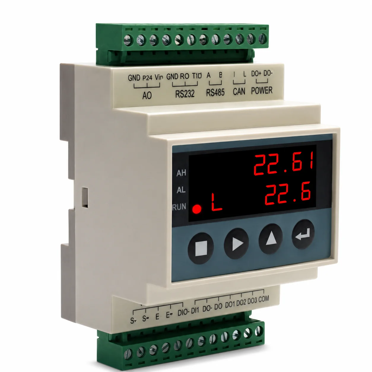
For an analogue strain-gauge system, the indicator or transmitter must provide suitable excitation and accept the total bridge load created by the number of connected cells. The designer should verify permitted input resistance, excitation voltage, sense-wire arrangement, cable length, shielding, grounding, junction-box method, and surge protection. Adding more parallel cells can change the electrical load even when the mechanical capacity appears correct.
Signal level matters in noisy environments. Routing a low-level sensor cable alongside motor conductors, variable-frequency-drive output, welding leads, or radio equipment can create intermittent errors that disappear during a quiet calibration visit. Specify separation, shielding, bonding, enclosure entry, and the point at which the signal is converted or digitised. Record these decisions on the wiring drawing.
Digital load cells add diagnostics and network functions in some systems, but they also introduce protocol, addressing, configuration, firmware, spare-part, and cybersecurity questions. "Digital" does not guarantee open interoperability. Procurement should request the protocol version, topology, replacement procedure, configuration backup, diagnostic access, failure behaviour, and ownership of service software.
Most importantly, separate a live weight value from an accepted business record. An indicator may display a stable value while an ERP transaction fails, or a PLC may read a number without knowing whether tare, units, motion, overload, or invalid status changed. Those integration semantics belong in the project's data specification, not in a generic promise attached to the load cell.
Treat legal-for-trade as a complete-instrument question
A certified load cell is not the same thing as an approved scale. For regulated use, authorities generally evaluate the complete measuring instrument and its approved components, markings, installation, sealing, software, and verification status under the applicable national system.
OIML R 60 concerns load cells. OIML R 76 concerns non-automatic weighing instruments. In the United States, NIST Handbook 44 provides specifications, tolerances, and technical requirements that are adopted and administered through relevant jurisdictions; its 2026 edition includes scale marking and device requirements. These documents are not global sales certificates, and their existence does not establish that a particular FMSCales product is approved.
Before ordering for regulated use, ask for:
- the exact type-evaluation or certificate number;
- issuing authority and current status;
- exact model, capacity, accuracy class, variant, cable, and load-transmission coverage;
- the complete instrument certificate or approval, not only a component document;
- local additional requirements;
- initial verification, installation, sealing, and subsequent-verification responsibilities;
- required markings and documentation;
- treatment of software, printers, remote displays, and connected systems.
If the supplier cannot map the quoted configuration to the certificate scope, treat the legal-use status as unconfirmed. The safe commercial wording is "approval to be confirmed for the exact model and market," not "OIML compliant everywhere."
Apply a different review to each scale architecture
Platform and floor scales
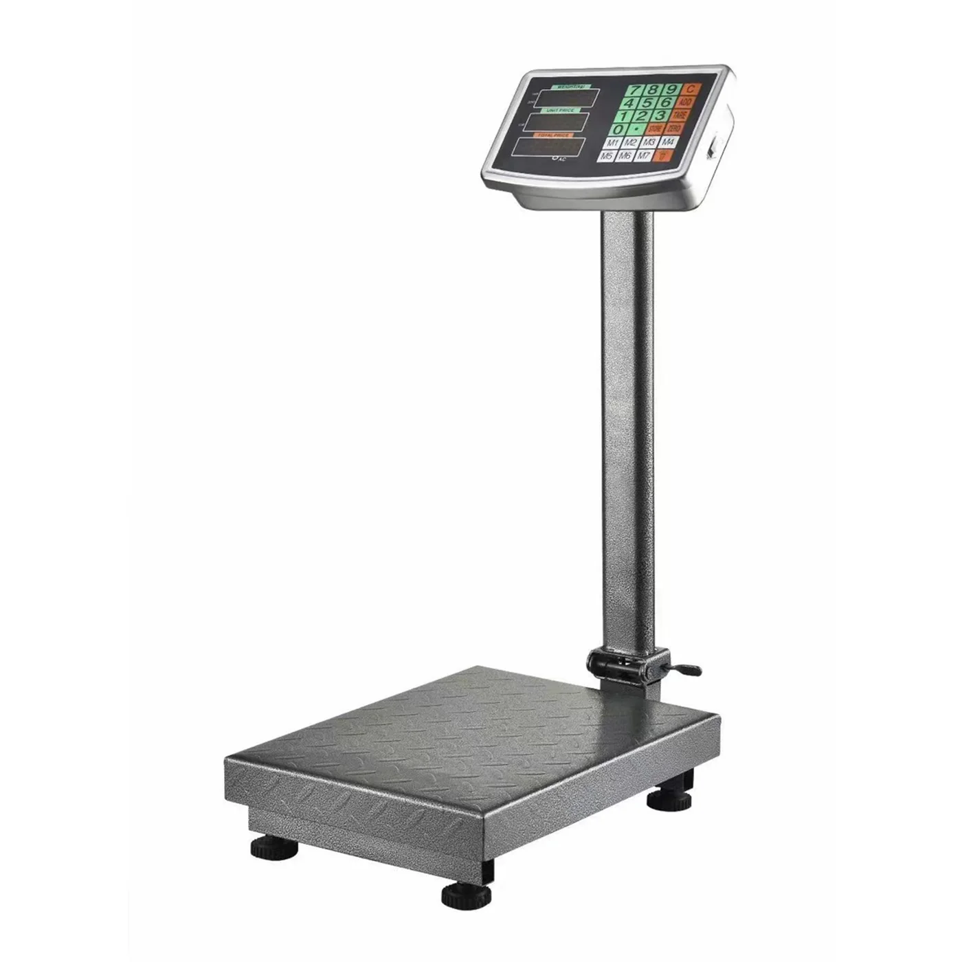
Check platform dimensions, load entry, ramps or pit, pallet-truck wheel paths, corner loading, overload stops, cleaning access, and freedom from binding. A single-point cell may suit some platforms, while multi-cell arrangements suit others; the manufacturer's approved platform size and mounting arrangement matter.
Hoppers and vessels
Map every pipe, agitator, flexible connection, check rod, ladder, service platform, and thermal movement. Decide whether all supports are weighed. Document fill pattern and centre-of-gravity change. Verify lift-off and lateral restraints independently from the measurement function.
Truck scales
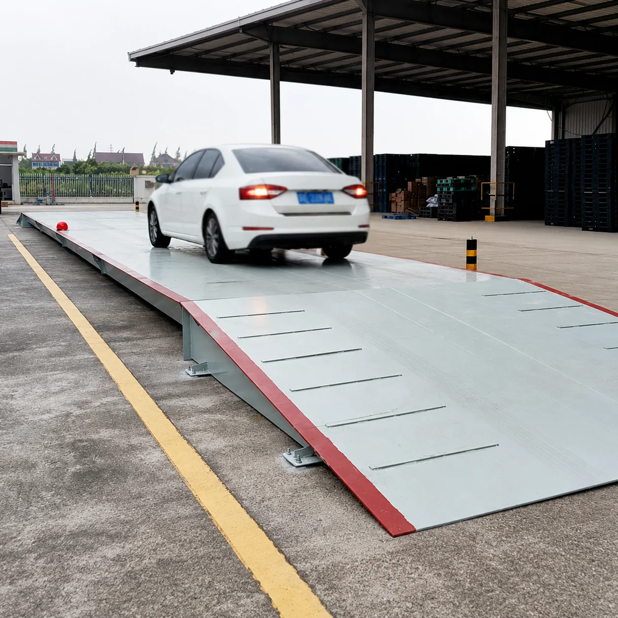
Review maximum axle and gross loads, bridge modules, foundation, traffic direction, braking, approach, lightning, drainage, load-cell access, and legal-control requirements. Vehicle-scale cell selection should not be reduced to total deck capacity divided by the number of supports.
Suspended and tension systems
Review rigging, alignment, anti-rotation, dynamic loading, fatigue, secondary retention, and safe access. A weighing sensor does not replace lifting hardware design or statutory lifting inspection.
Process and machinery integration
Define cycle rate, shock, vibration, control interlocks, maintenance access, invalid-state handling, and how calibration can be applied without dismantling production equipment. If the sensor also performs a machine-safety function, that function requires its own safety engineering and validation.
Use a gated procurement and acceptance process
A disciplined project can be organised into six gates.
Gate 1 — Load-case approval. The buyer and designer approve the operating, abnormal, environmental, and service loads. Assumptions are written down.
Gate 2 — Mechanical concept. The supplier provides sensor and mounting drawings. The structure, restraints, thermal movement, cable route, and replacement method are reviewed before fabrication.
Gate 3 — Electrical and data design. The indicator compatibility, total bridge load, wiring, earthing, surge protection, units, status flags, and downstream record ownership are documented.
Gate 4 — Documentation review. Data sheets, manuals, certificates, drawings, declarations, serialisation, spare-parts policy, and software requirements are matched to the exact quoted items.
Gate 5 — Installation inspection. The site records model and serial numbers, orientation, mounting condition, bolt work, platform freedom, restraint gaps, junction-box condition, cable route, and environmental sealing before calibration.
Gate 6 — Calibration and acceptance. The agreed reference, load points, positions, repeat runs, operating conditions, tolerance, legal verification where applicable, and result records are completed. Failed results trigger diagnosis, not automatic adjustment.
This process makes comparison easier because each bidder responds to the same technical package. It also protects the buyer from a common project failure: receiving a sensor that looks suitable on paper but cannot be installed, calibrated, verified, or replaced as intended.
Common mistakes that should stop approval
- Selecting by rated capacity and price without a load-case drawing.
- Comparing error terms that use different definitions or test conditions.
- Assuming a component certificate makes the complete scale legal for trade.
- Ignoring dead load, corner load, impact, uplift, thermal growth, or pipe force.
- Using the load cell as a structural stop or machine-safety device without engineering validation.
- Changing cable length, connector, mount, or junction-box arrangement without checking the approved design and calibration impact.
- Treating an IP code as proof against every washdown, submersion, corrosion, or condensation condition.
- Calibrating around mechanical binding or an unstable foundation.
- Accepting a digital protocol name without a register map, version, status definition, backup, and replacement procedure.
- Ordering spares by capacity alone rather than exact model, output, wiring, approval, mounting, and configuration.
What to include in a load-cell RFQ
Send enough information for the supplier to reject an unsuitable concept, not just enough to produce a price.
- Scale type, process description, and decision based on the weight.
- Structure drawing with support points, dimensions, and load entry.
- Dead load, normal range, maximum load, distribution, impact, uplift, and side-load assumptions.
- Number of sensors and preferred mounting or movement concept, if already designed.
- Environment: indoor/outdoor, temperature, washdown, corrosion, dust, submersion, vibration, hazardous-area status.
- Required indication, units, update behaviour, and acceptance method.
- Existing or proposed indicator, excitation, input, junction box, cable distance, and interface requirements.
- Market and intended use, including whether legal-for-trade approval is required.
- Documentation: drawings, manual, calibration data, certificate scope, material information, wiring, spare-parts list, and configuration backup.
- Site photos and maintenance-access constraints.
FMSCales can review a submitted load case against available product documentation, but final selection remains conditional on the exact model, structure, installation, indicator, market, and acceptance requirement. A useful response should identify both the proposed route and the information still missing; a model number without those conditions is not a complete engineering answer.
The buyer's final decision
Approve the load cell only when four things agree: the mechanical load path, the electrical signal chain, the environmental construction, and the metrological or legal documentation. If one remains unresolved, the system is not ready for purchase simply because the sensor capacity looks sufficient.
The practical next step is to issue one controlled RFQ package containing the structure, load case, environment, indicator, intended use, market, and acceptance test. That package gives engineering, procurement, the supplier, and the commissioning team a common basis for comparison—and leaves fewer surprises for the calibration visit.
Select the sensor and mechanical application together
A load cell is part of a force-introduction system. Capacity, load direction, mounting hardware, movement, environmental protection, cable arrangement, signal, approval scope and service access must be reviewed as one configuration.
- Define the force direction and worst credible load case
- Select mounts and restraints that introduce load as intended
- Check signal, excitation, cable length, junction arrangement and indicator compatibility
- Plan cornering, calibration, environmental sealing and replacement traceability
Buyer-task questions
Can two load cells with the same capacity be interchanged?
Not safely from capacity alone. Mechanical dimensions, force direction, output, wiring, accuracy class, environmental rating, approval and mounting can differ.
When is an S-beam route considered?
It may suit tension or compression force paths when the exact mechanics, alignment, overload protection and signal chain support that use. Confirm the model data rather than selecting from shape alone.
References
The following official and first-party sources support the bounded examples, standards context and evaluation methods used in this guide. They do not verify an FMSCales configuration.
 Load Cells
 Load Cell Accessories
 Truck Scales
 Platform Scales
 Weighing Indicators