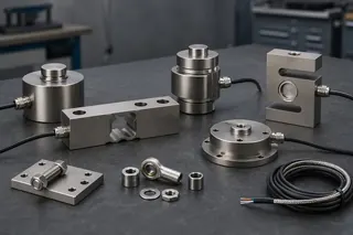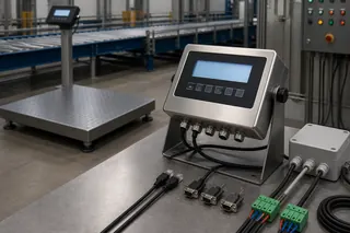
Do not replace the nearest load cell simply because a scale drifts or jumps. First define the symptom and preserve the as-found state. Then isolate the system in order: load receptor and restraints, individual mounting points, cable and junction box, excitation and signal circuit, indicator and power, and finally environmental or process influences. Condemn a sensor only when repeatable measurements and physical evidence follow that sensor.
Replacing the nearest load cell is tempting when a scale starts to jump or drift. It is also a common way to spend money without removing the fault. A tight check rod, water in the junction box, a damaged home-run cable, unstable excitation, or product bridging a hopper can produce the same complaint at the indicator.
Start with the symptom and work through the system in the order that preserves evidence: load receptor and restraints, individual mounting points, cable and junction box, excitation and signal circuit, indicator and power, then environmental and process influences. Condemn a sensor when repeatable measurements and physical evidence follow that sensor, rather than when its symptom merely resembles an earlier failure.
The sequence applies mainly to analogue strain-gauge load cells in platform, floor, vessel, hopper, truck, and similar industrial scales. An unknown model still requires its own wiring diagram, mounting instructions, calibration evidence, and safe-work method. Work beneath a raised receptor, loaded-mount adjustment, restraint changes, certified seals, and energized testing are outside this general diagnostic sequence unless the site has authorized qualified people and appropriate protection.
If the project has not yet selected a sensor architecture, begin with the industrial load-cell selection guide rather than using a fault-isolation article as a buying specification. Confirm candidate hardware and documentation through the load-cell product family before applying any model-specific threshold.
Define the symptom before touching the scale
“The scale is inaccurate” is not a diagnostic description. Ask the operator to demonstrate the problem without changing settings. Record what the display does, when it begins, and what restores normal operation. The distinction between a constant offset, a slowly moving zero, a position-dependent error, and random noise points to different layers.
| Observed symptom | First layers to examine | Evidence worth preserving |
|---|---|---|
| Constant offset after a known event | Debris, binding, zero procedure, changed dead load, mechanical damage | As-found display, recent maintenance, empty-receptor condition |
| Zero drifts in one direction | Temperature, moisture, creep, binding, damaged cell, unstable excitation | Time-stamped zero trend, temperature, washdown/weather history |
| Reading jumps or flickers | Loose connection, damaged cable, moisture, electrical noise, unstable power, vibration | Video of display, indicator status, nearby motor/VFD activity |
| Different value at different corners | Mount freedom, foundation, load introduction, junction-box trim, individual cell response | Marked test positions, repeat runs in the same order |
| Cannot calibrate or span is implausible | Wrong units/capacity, configuration, excitation, wiring polarity, mechanical shunt, failed cell | Configuration backup, reference-load identity, raw signal if authorized |
| Error appears only after rain or washdown | Cable entry, junction box, connector, seal damage, condensation | Photos before drying, insulation result using approved method |
| Error appears only during production | Pipe force, vibration, material buildup, thermal gradient, EMI, operating sequence | Planned idle-versus-running comparison with conditions recorded |
Write a one-sentence problem statement: “With the receptor empty/full and the process idle/running, the indicated value changes by ___ over ___, beginning after ___ and recovering when ___.” If the team cannot complete that sentence, collect observations before adjusting anything.
Also identify the business consequence. A process trend used for internal control, a batch cutoff, and a legally controlled commercial result require different evidence and authorization. In a regulated instrument, breaking a seal, changing calibration parameters, or replacing an approved component may require an authorized service route and reverification. NIST Handbook 44 is relevant to many US commercial devices but is adopted and administered by jurisdictions; it is not a worldwide repair permission.[5]
Secure the system and preserve the as-found state
Troubleshooting can introduce new faults. Before disconnecting wires or moving hardware, capture:
- scale, indicator, junction-box, and load-cell model/serial identification;
- indicator firmware and configuration backup where the approved procedure permits it;
- displayed gross/net/tare, unit, motion, zero, range, and error states;
- time, ambient condition, process condition, recent washdown or weather;
- recent welding, lightning, power work, cable work, structural repair, overload, impact, or firmware change;
- photographs of each mounting point, restraint, cable route, gland, connector, and junction-box interior before cleaning;
- seal status and legal-for-trade status;
- reference load identification, traceability, and suitability for the intended test.
If there is cracked steel, a displaced mount, bent load receptor, loose foundation, damaged lifting support, burnt wiring, evidence of lightning, hazardous-atmosphere concern, or an overload event beyond the documented structure limit, stop. Isolate the equipment and involve the responsible mechanical, electrical, safety, metrology, or OEM authority. A weight display cannot declare a damaged structure safe.
Use lockout/tagout and site access control as required. Never place a person under a receptor supported only by jacks or hydraulics. Never megohm-test a load cell while it remains connected to an indicator or other electronics unless the equipment manufacturer explicitly specifies that method. Never inject an unapproved voltage into a bridge circuit. METTLER TOLEDO's terminal documentation, for example, instructs users to remove power and wait before connecting or disconnecting internal electronic wiring and restricts service to qualified personnel; that model-specific warning illustrates why the actual manual must govern.[4]
Layer 1: prove that the load can move as designed
Many “bad load cell” calls are force-path problems. The sensor measures force delivered through the structure. Anything that carries, diverts, restrains, or intermittently releases that force can change the indicated result.
With the equipment safely isolated, inspect for material packed beneath a platform, product bridging a hopper, a tight bumper, seized check rod, touching ramp, bent flexure, frozen bearing, corroded rocker, pipe strain, hose tension, cable pulled tight, or transport bolt left engaged. Look for shiny witness marks showing contact. Check whether all feet and supports remain seated and whether a platform rocks. Compare mount orientation with the exact drawing. Interface's installation guidance emphasizes mounting surface, hardware, orientation, cable condition, and physical inspection because mechanical installation and electrical integrity jointly determine performance.[3]
Do not “free” a structure by loosening restraints at random. Restraints may control wind, uplift, vehicle braking, seismic movement, or another hazardous load. Their required clearances and preload are design-specific. A competent person must decide whether an observed contact is an unintended force shunt or a necessary safety feature.
For vessels, compare the empty and operating condition. Pipework may be free when cold and bind when hot; a flexible connection may become packed with product; an agitator may introduce torque; one support may unload as the structure expands. For vehicle and floor scales, inspect approaches, modules, end checks, dirt accumulation, and foundation drainage. For a bench scale, examine the platform stops and confirm that the load is applied within the specified area.
Repeatability is the useful separator. Apply the same suitable test load at the same location several times, fully removing it between trials. If values do not repeat, adjustment is premature. If they repeat at one position but differ consistently among positions, proceed to mount and corner isolation. If the result changes only when a motor, pump, or conveyor runs, preserve that correlation and investigate both mechanical vibration and electrical interference.
Layer 2: compare corners and individual support behaviour
On a multi-cell scale, a planned position test can show which support behaves differently. Use a test load and placement method appropriate to the scale, capacity, applicable standard, and site procedure. Mark the positions. Approach them in a consistent sequence, then reverse the sequence to detect hysteresis or binding. Record the raw indicated value; leave trim settings unchanged between readings.
A low or high corner does not prove the adjacent cell is faulty. The cause can be an uneven foundation, mount misalignment, a mechanical shunt, a damaged summing path, cable resistance, a trim setting, or a sensor. Swap tests can be powerful but must be planned: changing two cell channels at the junction box may reveal whether the fault follows the sensor/cable or stays with the channel, yet incorrect swapping can reverse polarity, disturb sealing, or create a new wiring fault. Only a qualified technician using the correct diagram should do it.
The Rice Lake load-cell handbook recommends a sequence that includes physical inspection, zero balance, bridge resistance, and resistance to ground.[1] That order is important. Electrical measurements are more meaningful after the structure and cable have been examined and the exact lead functions are known.
If corner values are repeatable and the mechanics are sound, junction-box adjustment may be appropriate—but only after confirming that every cell is healthy and the chosen trimming method matches the box. Trimming an unstable or damaged channel merely forces one test point to agree temporarily. It can reduce signal margin and hide a deteriorating fault. Preserve the initial potentiometer positions or measured settings before any authorized adjustment.
Layer 3: inspect the cable and junction box before measuring the bridge
Follow each cable from the cell to the box. Look for crushed sections, tight bends, cuts, abrasion, rodent damage, chemical attack, stretched glands, unsupported connectors, unauthorised splices, and routes shared with motor or welding conductors. A cut jacket in a wet area can allow moisture to travel along the cable toward the sensing element. Rice Lake specifically calls out cuts, crimps, abrasion, sealing damage, corrosion, and contamination during physical inspection.[1]
Open the junction box only when permitted and safe. Photograph it first. Check for condensation, water tracks, corrosion, conductive dust, insects, loose terminals, damaged glands, green or blackened copper, solder residue, and mismatched jumpers. Do not dry or clean it before documenting the evidence; the moisture pattern may identify the ingress route. Flintec's LCT-11 guide directs technicians investigating erratic results to check the junction box for moisture, dirt, leakage paths, soldering residue, and cable integrity before disconnecting individual cells.[2]
Verify every conductor by function, not colour. There is no universal colour code. Excitation positive/negative, signal positive/negative, sense positive/negative, and shield must match the exact cell and indicator documentation. A replacement cell from another family may use the same colours for different functions.
Shield termination is system-specific. Connecting it at both ends without design intent can create a ground loop; leaving it floating when the manufacturer expects a defined termination can reduce immunity. Do not bond a signal conductor or cell body as a substitute for the prescribed shield and protective-earth arrangement.
Layer 4: use electrical tests as comparisons, not universal pass/fail numbers
The future dedicated multimeter guide should contain the detailed setup. At troubleshooting level, understand what each test can and cannot prove.
Excitation at the indicator and at the cell shows whether the bridge is being powered and whether cable or connection drop is plausible. Measure only within the equipment's safe low-voltage procedure. A correct nominal excitation does not prove the signal pair or mechanics are healthy.
Signal output under no load and a known load can reveal polarity, gross zero shift, dead channels, and whether output changes smoothly in the normal direction. Compare measured millivolts with excitation and the exact rated output. Do not convert that alone into an accuracy claim; structure, calibration, and environmental effects remain.
Input and output bridge resistance can identify open circuits, shorts, or large imbalance when compared with the exact data sheet and cable arrangement. Lead resistance and six-wire sense circuits affect readings. A resistance that looks plausible does not exclude moisture leakage, mechanical damage, or a performance error under load.
Resistance from bridge conductors to body/shield can reveal insulation deterioration. The test voltage and connection method matter. A generic insulation tester can damage connected electronics or exceed a manufacturer's permitted test. Isolate the cell exactly as instructed. Flintec's diagnostic example expects very high insulation for its described test arrangement, but its number is not a universal acceptance limit for every cell or field meter.[2]
Zero balance is evaluated with the cell truly unloaded or dead load correctly accounted for. Residual force, trapped material, pipe strain, and mount preload can imitate a shifted zero. Rice Lake notes that zero-balance testing is useful for identifying physical distortion from overload, shock, or fatigue, but the manufacturer's specification and test condition control.[1]
Record meter make, model, range, calibration status, lead compensation where relevant, ambient conditions, conductor combinations, excitation, load, and time. A table of readings is more useful than “cell tested OK.” Compare like-for-like cells within the same scale as well as the data sheet. One channel that differs materially from three peers deserves investigation even when all four readings appear superficially close.
Layer 5: separate indicator, power, and interference faults
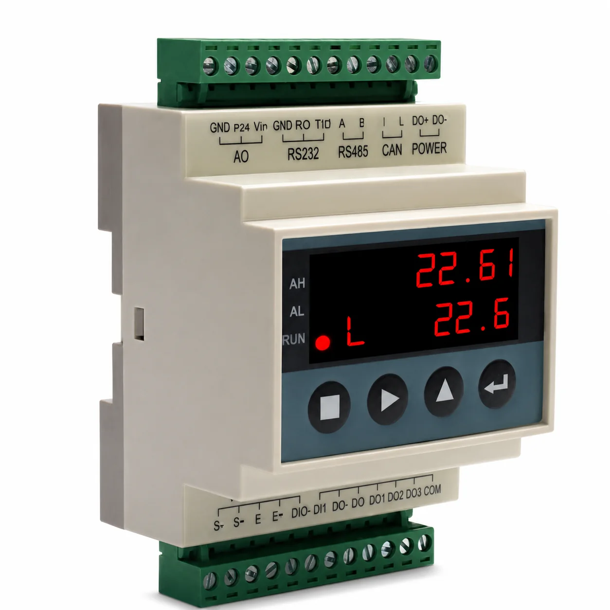
If all cells combined show a problem, connect a manufacturer-approved simulator or known-good test source only if the service procedure allows it. A stable simulator at the indicator can separate the terminal from the field circuit, but it cannot prove that the real structure is sound. Likewise, a portable tester connected to the home-run cable can separate the field system from the indicator, but the tester's excitation, filtering, and input characteristics may differ.
Check supply voltage, protective earth, enclosure condition, connectors, configuration, filters, sample/update settings, motion band, zero tracking, and channel assignment against the configuration backup. Do not recalibrate merely because a parameter looks unfamiliar. Determine who changed it and why.
Correlate unstable readings with variable-frequency drives, contactors, radio transmitters, welding, chargers, pumps, lightning events, and generator transfer. Inspect cable segregation and shield routing. When operations and safety rules permit, a planned comparison with one process item stopped can be informative. That does not authorize bypassing protection, opening energized cabinets, or changing grounding.
If the indicator shows overload, underload, ADC, excitation, or load-cell-connection errors, use the exact manual. Error names do not have universal thresholds. An overload message may result from a real load, shifted zero, reversed or open signal, excessive input, wrong calibration, or failed electronics. Record the code and state before cycling power.
Layer 6: recreate environmental and time-dependent conditions
An intermittent fault may disappear on a dry workbench. Trend the raw indication or stable display against time, temperature, humidity, rainfall, washdown, sunlight, process heat, and equipment state. If operation permits a planned cold start, record the warm-up rather than relying on memory. Comparing empty-scale drift with a stable applied load can help separate zero-path changes from signal noise, although the comparison alone cannot prove the cause.
Moisture faults may change as insulation dries. Thermal gradients can bend a receptor or load supports unevenly. Material buildup can grow during a shift. Creep and return-to-zero behaviour depend on load history and time. OIML R 60:2021 defines metrological characteristics and performance tests for load cells under specified conditions; those controlled tests explain why a single field reading cannot establish a cell's class or complete-system compliance.[4]
Do not heat a sealed cell, drill a housing, cut a moulded cable, or apply chemicals to accelerate diagnosis. Such actions can destroy evidence, sealing, calibration compensation, approval scope, and warranty.
Decide the corrective action from the isolated layer
Use an evidence gate before acting:
- Mechanical cause confirmed: correct the structure or mount under an approved design, then inspect all sensors and recalibrate/verify as required.
- Cable or junction-box cause confirmed: replace or repair only by the approved method; restore sealing, routing, shielding, identification, and strain relief; then retest the complete system.
- Individual cell electrically or physically failed: match exact model, capacity, output, approval scope, cable, and mounting requirements. Replacing one cell in a set may require compatibility review and complete adjustment/verification.
- Indicator or configuration cause confirmed: restore from a controlled backup or follow the manufacturer service process; preserve audit trails and seals.
- Environment/process cause confirmed: change drainage, guarding, cleaning, cable route, temperature control, operating sequence, or maintenance interval rather than repeatedly zeroing the symptom.
- Evidence remains ambiguous: do not trim or recalibrate to make one test pass. Escalate with the diagnostic record.
After any correction, repeat the as-found tests in the same positions and conditions, then complete the applicable calibration, corner, repeatability, increasing/decreasing load, and operational tests. For a regulated device, involve the responsible authority or licensed/registered service route as required. “Display returned to zero” is not a complete return-to-service criterion.
Build a service pack that shortens the next diagnostic visit
Send the support team:
- Scale architecture, capacity, division, use, and regulatory status.
- Load-cell, mount, junction-box, and indicator model/serial information.
- Wiring drawings, manuals, certificate/data-sheet revision, and configuration backup.
- Exact symptom statement and first known occurrence.
- Recent overload, impact, weather, washdown, welding, repair, power, or configuration events.
- Photographs before disturbance.
- Position-test results with load identity and sequence.
- Excitation, signal, resistance, and insulation results with method and meter details.
- Conditions under which the fault appears or disappears.
- Actions already taken and whether seals or settings changed.
FMSCales can use that pack to compare the observed system with available product documents and identify information still required. This is not a promise that remote review can approve a repair or replace an on-site safety/metrology assessment.
Stop self-troubleshooting when the risk exceeds the evidence
Stop and escalate for structural damage, uncertain support of a raised receptor, suspected overload beyond design, lightning or burnt electronics, hazardous-area equipment, broken legal seals, inaccessible manufacturer instructions, unknown wire functions, unstable insulation test conditions, repeated component failure, or any need to work energized beyond the technician's authorization. Also stop when an adjustment improves one point but worsens another; that is evidence of an unresolved system problem.
Speed comes from avoiding resets and part swaps that erase clues. Protect people, preserve the as-found state, test one layer at a time, and leave the next technician a clear reason for every correction.
Next step: send the symptom statement, system drawings, model documents, photos, position-test record, and authorized electrical measurements through technical support or the request-a-quote route. The useful output is a model-specific diagnostic plan with confirmed stop-work boundaries—not a generic instruction to turn a trim pot or replace the nearest sensor.
Separate mechanical, electrical and measurement evidence
Effective scale load cell troubleshooting begins with the symptom and operating condition, then checks the load path, mounting, cabling, junction box, excitation and signal without changing settings prematurely. Preserve raw readings and isolate one cause at a time.
- Describe whether the fault is drift, noise, non-linearity, no return to zero or a dead channel
- Inspect restraints, binding, debris, mounts and force direction before electrical adjustment
- Compare excitation and signal consistently and avoid unsafe live work
- Restore seals, calibration and verification only through the approved service route
Buyer-task questions
Why can a sound load cell still produce a bad scale result?
The complete result also depends on load introduction, mounts, restraints, cables, junction boxes, excitation, indicator configuration, environment and the test method.
Should individual load cells be swapped during diagnosis?
Only under an approved safe procedure. Uncontrolled swapping can introduce wiring errors, overload a component or erase useful evidence.
References
The following official and first-party sources support the bounded examples, standards context and evaluation methods used in this guide. They do not verify an FMSCales configuration.
 Load Cells
 Load Cell Accessories
 Weighing Indicators
 Platform Scales