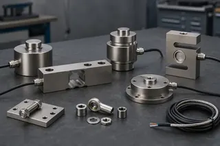
A weighing indicator should be selected from the job it must perform, not from the size of its display or the number of protocol logos on a data sheet. The buyer first needs to define five behaviours: how the weight is measured, what the operator must decide, what the machine must do, what record must be retained, and what happens when the signal or network is invalid. Those behaviours determine the required load-cell input, metrological functions, front-panel controls, outputs, communications, enclosure, software, and approval scope.
This guide covers indicators and weighing terminals used with industrial scales, platforms, vessels, vehicle scales, and process systems. It does not state that any FMSCales indicator supports a particular input, protocol, accuracy class, or legal-for-trade market. Those details must be confirmed against the exact model, firmware, certificate, connected load receptor, and jurisdiction.
Define the indicator's role before comparing models
The word indicator can describe several very different devices. One unit may simply convert a strain-gauge signal into a local weight display. Another may control batching, print a ticket, store transactions, exchange data with a PLC, or act as a gateway to an ERP system. A third may be a module within a legally controlled non-automatic weighing instrument.
Start the specification by assigning responsibilities. For each function, identify whether the indicator, PLC, local application, cloud service, operator, or another system owns it.
| Required behaviour | Questions the buyer must answer |
|---|---|
| Measurement | Which load receptor and sensors are connected? What units, ranges, divisions, and stability rules are required? |
| Operator decision | What must the operator see, enter, accept, reject, print, or correct? |
| Machine control | Which setpoints, interlocks, feeders, valves, lights, or alarms depend on weight? |
| Business record | Which identifier, gross/tare/net values, status, time, and user action form a completed transaction? |
| Exception handling | What happens during motion, overload, underload, sensor fault, power loss, network loss, duplicate transmission, or failed print? |
| Service | Who can calibrate, change configuration, restore a backup, diagnose a channel, and approve return to operation? |
This exercise prevents an expensive but common mismatch: a device that can display weight but cannot create the record the buyer needs, or a terminal with extensive software functions that cannot accept the installed load-cell circuit.
Separate live weight, accepted weight, and business transaction
These three data objects are not interchangeable.
Live weight is the current measured value, which may change continuously and may be unstable, outside range, or subject to a fault.
Accepted weight is a value captured under defined conditions, such as stable indication, an operator command, a digital trigger, or a completed automatic cycle. It should carry units and status.
Business transaction combines one or more accepted weights with context such as vehicle, pallet, batch, product, order, operator, gross/tare/net relationship, timestamp, and posting state.
An indicator may handle one, two, or all three. Procurement should not assume that a communications port turns a live display into an auditable transaction. If a PLC reads the latest register while the scale is moving, it may record a number that was never accepted. If an ERP retries after a network failure without a unique transaction ID, it may create a duplicate. The existing FMSCales data-integration guide should remain the primary design reference for record ownership, acknowledgements, offline queues, and ERP/WMS semantics; this article focuses on choosing the indicator that can participate in that design.
Confirm the load-cell input as an electrical circuit
For an analogue strain-gauge system, compatibility is more than matching a millivolt-per-volt description. The indicator provides excitation to the load-cell bridge and measures a small differential signal. The complete connected circuit must be within the indicator manufacturer's limits.
Ask for and compare the following on both sides of the connection:
- excitation voltage or range;
- permitted total load-cell impedance or minimum resistance;
- number of load cells and their input resistance;
- four-wire or six-wire connection and remote-sense support;
- rated load-cell output and usable input-signal range;
- input resolution and conversion behaviour under the intended conditions;
- cable length, conductor size, shielding, junction boxes, and connector limitations;
- zero-signal range and dead-load compensation;
- approved or tested load-cell combinations where regulated use is intended;
- surge, lightning, electrostatic, and electromagnetic protection requirements.
Parallel load cells change the electrical load seen by the excitation supply. Long cables introduce voltage drop and more opportunity for interference. Sense conductors can compensate for some cable effects when the indicator and wiring arrangement support them, but they do not correct poor shielding, moisture in a junction box, an overloaded excitation supply, or a damaged bridge.
Do not compare only the number of display counts. A large internal count does not prove that the complete scale can deliver an equally fine stable division in the real environment. Mechanical noise, vibration, load-cell output, dead load, temperature, filtering, conversion, and approval rules all affect the useful result. The buyer should state the required application result and ask the supplier to demonstrate it with the proposed load receptor and sensors.
Digital load cells or weighing modules require a different review. Confirm protocol, physical layer, topology, addressing, maximum nodes, update behaviour, diagnostics, replacement procedure, firmware compatibility, configuration ownership, and whether tools or licence keys are needed. A proprietary digital bus may be entirely suitable, but the spare-parts and service plan must acknowledge that dependency.
Specify weighing behaviour, not just capacity and division
An indicator's core functions should be written as operating rules. Typical subjects include zero setting, zero tracking, tare, preset tare, motion detection, stable indication, multiple ranges or intervals, negative weight, overload, unit selection, accumulation, counting, peak hold, checkweighing, printing, and calibration access.
The buyer should define who may invoke each function and what the function changes. For example:
- Is tare entered by the operator, received from a database, measured from an empty container, or fixed by product?
- Can units be changed during a transaction?
- Is a stable indication required before printing or sending a result?
- How is an overload represented on the display, output, printer, and network?
- Does zero tracking operate in the intended process, and under what restrictions?
- If there are multiple ranges, how does the instrument return to a lower range?
- Are totals informative process values or controlled commercial records?
OIML R 76-1:2006 addresses metrological and technical requirements for non-automatic weighing instruments, including indication, zero-setting, tare, electronic instruments, software-controlled devices, markings, and metrological controls. It is a reference framework, not proof that a quoted terminal or completed scale is approved. The exact certificate and national implementation must be checked.
Automatic filling, catchweighing, continuous totalising, and other automatic functions may fall under different requirements. A non-automatic indicator should not be assumed suitable for an automatic instrument merely because it has relay outputs or a fast update mode.
Design the operator interaction around real work
Front-panel design affects error rates and serviceability. A bright display is useful, but the buyer should examine the full interaction:
- viewing distance, lighting, dust, condensation, gloves, and language;
- dedicated keys versus nested menus;
- confirmation before clearing totals or changing tare;
- visible units, gross/net state, motion, zero, range, overload, and fault status;
- entry and validation of IDs, recipes, vehicles, or products;
- user roles and protection of calibration or legal parameters;
- print preview, reprint authority, and duplicate marking;
- behaviour after power restoration;
- local instructions for invalid or rejected weighing.
Consider the consequences of a plausible mistake. If an operator enters a preset tare in the wrong unit, can the system detect it? If a reprint looks identical to an original ticket, can the transaction be counted twice? If the display returns after a power cut, is the prior batch still active? If a remote command changes zero or tare, is that action visible and logged?
For multilingual sites, avoid assuming that a translated marketing interface means the operational prompts, print templates, error messages, manuals, and service software are also translated. Verify the exact firmware language set and have an actual user review critical terminology.
Select I/O by the control sequence
Digital inputs and relay or transistor outputs should be derived from a sequence diagram. List each signal, normal state, trigger condition, duration, interlock, acknowledgement, fault state, and electrical characteristic.
Common uses include remote zero, tare, print, start, stop, accept, reject, gate control, feeder control, stable-weight output, high/low setpoints, alarm, and traffic lights. Names alone are not enough. A "stable" output might indicate stability at the display while the process needs a completed accepted record. A setpoint may change state immediately or only after filtering and delay. A relay may be unsuitable for the required switching frequency or fail-safe state.
For analogue outputs, define whether the signal represents gross, net, live, filtered, or accepted weight; its scaling; behaviour below zero and above range; update rate; isolation; fault indication; and calibration method. A 4–20 mA nameplate does not explain whether a broken sensor cable drives the output low, high, last-value, or to a configured fault level.
If the indicator directly controls material movement, decide whether it is the correct place for the process logic. Some projects are better served by keeping metrological measurement in the indicator and sequence control in a PLC, with a documented interface between them. Safety-related interlocks require separate risk assessment and validated safety architecture; a general-purpose weight relay should not be assumed to perform a safety function.
Treat protocol support as the start of integration
RS-232, RS-485, Ethernet, USB, Modbus, and OPC UA describe different parts of a communication arrangement. A connector or protocol name does not define the application data.
For each interface, request:
- physical connection and isolation;
- protocol and version;
- client/server or master/slave role;
- addressing and network settings;
- register map, data types, byte and word order;
- units, decimal scaling, sign, range, and status flags;
- live versus latched or registered weight;
- commands and their authorisation;
- update, timeout, retry, and acknowledgement behaviour;
- error codes and invalid-state representation;
- clock and timestamp ownership;
- configuration backup and firmware compatibility;
- a test procedure and sample messages.
The Modbus Organization's Application Protocol Specification V1.1b3 defines function codes and the protocol data model. It does not standardise a universal register address for "stable net weight" in every scale. That mapping remains device-specific unless another agreed profile applies. The buyer therefore needs the indicator's actual register documentation and a version-controlled integration test.
OPC 40200, the OPC UA Companion Specification for Weighing Technology, provides a manufacturer-independent information model for weighing devices and related functions. Version 2.00 was released in 2025. Its existence can improve common understanding when both sides implement the relevant profile, but an "OPC UA" option should still be checked for the supported specification version, scale type, conformance units, security configuration, and client interoperability.
For simple serial output, obtain the exact frame format and trigger behaviour. Many projects fail because a receiving system expects one line per accepted weighing while the indicator streams live values continuously, or because the receiver cannot distinguish motion, overload, and valid zero.
Include records, printers, and identifiers in the specification
If the terminal stores or prints transactions, define the record before selecting memory size or printer type. A useful weighing record may include:
- unique transaction ID;
- device and site ID;
- product, vehicle, container, pallet, batch, or order ID;
- gross, tare, net, unit, and range;
- accepted/rejected/manual status;
- date, time, and time-zone rule;
- operator or lane;
- approval or exception status;
- original/reprint/correction relationship;
- software and configuration version where needed.
Decide how records are searched, exported, protected, corrected, backed up, and reconciled. "Stores 100,000 records" does not answer whether a power loss can interrupt a write, whether IDs are unique across devices, whether an export shows deleted or corrected transactions, or whether the storage is appropriate for the buyer's retention requirement.
Printing has similar hidden details: paper width, environmental protection, cutter, label or ticket layout, characters, barcode format, duplicate marking, consumables, driver support, and failure handling. If a printer is legally significant, confirm the approved relationship between instrument, software, and printed result.
Match the enclosure and power system to the site
Indicator location affects both usability and reliability. Record whether it will be panel-mounted, desk-mounted, wall-mounted, vehicle-mounted, or placed in an outdoor kiosk. Check temperature, condensation, sunlight, washdown, dust, corrosion, vibration, shock, electromagnetic disturbance, and hazardous-area classification.
An IP rating addresses specified ingress tests; it does not by itself establish resistance to chemicals, high-pressure cleaning, salt, ultraviolet exposure, condensation, or an improperly fitted cable gland. Review the full installed enclosure, including connectors, glands, doors, printer slots, mounting holes, and ventilation.
Specify supply voltage and frequency, DC range, battery type, charging, runtime test conditions, low-voltage behaviour, grounding, isolation, and power-loss recovery. In mobile equipment, cranking voltage, alternator noise, transients, and shutdown procedure may matter. In a fixed plant, UPS behaviour and controlled restart may be more important than nominal consumption.
Hazardous areas require an exact certificate and installation design for the complete equipment arrangement. Placing the indicator outside the hazardous area with approved barriers may be one route; using certified field equipment may be another. The quoted model, protection concept, area classification, barriers, load cells, cabling, glands, and local rules must all agree.
Check approval scope at module and complete-instrument level
Legal-for-trade suitability cannot be established from a logo or general statement. OIML R 76 includes provisions for indicators and digital data-processing devices as modules, plus compatibility considerations for a complete non-automatic weighing instrument. A module certificate does not automatically approve every combination of indicator, load cells, load receptor, software, printer, and market.
In the United States, the 2026 edition of NIST Handbook 44 contains scale specifications, tolerances, markings, installation, and use requirements that are administered through the applicable weights-and-measures authorities. Other jurisdictions use their own legislation, approvals, and verification processes.
For regulated use, request:
- exact certificate or certificate-of-conformance number;
- issuing body and current status;
- exact model, firmware, options, accuracy class, ranges, and interfaces in scope;
- compatible modules and any compatibility calculation;
- sealing, audit-trail, software, remote-display, and printer conditions;
- descriptive and verification markings;
- initial and subsequent verification responsibility;
- local additional requirements.
Do not assume that a firmware update, communication option, replacement indicator, remote command, or modified ticket is outside approval control. Confirm before change.
Compare candidates with an application matrix
Use a scored requirement matrix rather than a feature count. A simple structure is shown below.
| Decision area | Mandatory evidence | Acceptance question |
|---|---|---|
| Load-cell input | Electrical limits, wiring diagram, supported cells | Does the proposed circuit remain within every limit? |
| Weighing behaviour | Function description and operating sequence | Can the operator obtain and recognise a valid result? |
| I/O | Electrical data and timing behaviour | Do signals match the PLC and fail to a defined state? |
| Data interface | Protocol version, register/message map, sample frames | Can the receiver distinguish value, unit, state, and transaction? |
| Records and print | Sample record, export, correction and reprint rules | Is the output auditable for the buyer's process? |
| Environment | Enclosure, power, temperature, mounting, approvals | Is the complete installed unit suitable for the site? |
| Service | Backup, access roles, diagnostics, firmware and spares | Can a replacement be restored and verified without guesswork? |
| Legal use | Exact certificates and market mapping | Is the complete quoted instrument eligible for local approval and verification? |
Mark unsupported items as gaps. Do not reward a bidder for optional features that have no role in the operating sequence. The best indicator is the one that meets the controlled requirement with clear evidence and a maintainable service path.
Test the indicator before site handover
A factory or bench test should use the proposed indicator configuration and, where practical, a representative load-cell simulator or load receptor. A site acceptance test should then confirm the complete installed system.
Include at least the applicable tests:
- Model, firmware, option, certificate, and wiring verification.
- Power-up, restart, configuration restore, and low-power behaviour.
- Zero, tare, preset tare, units, range, motion, stable indication, overload, and negative-load behaviour.
- Representative load points and positions using the agreed reference method.
- Operator permissions, invalid entries, corrections, and reprints.
- Every digital input, output, setpoint, interlock, and fault state.
- Analogue-output scaling, update, isolation, and failure response.
- Protocol values, units, signs, status, commands, timeouts, reconnects, and duplicates.
- Stored and printed record reconciliation.
- Network loss, printer failure, sensor fault, and power interruption.
- Backup, replacement, restoration, and post-service verification.
- Legal verification and sealing where required.
A successful connection test is not an acceptance test. The project should demonstrate the correct value, in the correct state, reaching the correct destination, producing the intended action, and remaining traceable through a failure and recovery.
What to include in an indicator RFQ
Send the supplier a concise but complete application pack:
- scale type, load receptor, capacity, divisions, units, and intended use;
- load-cell model, quantity, output, resistance, wiring, cable, and junction box;
- required zero, tare, range, accumulation, printing, batching, or checkweighing behaviour;
- operator sequence, user roles, languages, identifiers, and sample screen or ticket;
- I/O list with voltage, current, timing, normal state, and fault state;
- communication interface, protocol version, role, message/register requirements, and network policy;
- sample accepted record and downstream ownership;
- enclosure, mounting, power, temperature, cleaning, vibration, corrosion, and hazardous-area requirements;
- market, legal-for-trade status, certificate and verification requirements;
- test, documentation, backup, spares, firmware, and support expectations.
FMSCales can compare this requirement pack with available indicator documentation. A responsible model recommendation should state what is supported, what needs an option, what remains unverified, and which functions belong in another system. It should not turn a list of ports into a promise of completed integration.
The buyer's final decision
Approve an indicator when its measurement input, weighing logic, operator workflow, control interfaces, data semantics, environmental construction, service path, and approval scope all support the same application. If one of those layers is undefined, more features will not close the gap.
The most useful next step is to provide the actual load-cell circuit, operating sequence, I/O list, sample record, network constraints, environment, and target market. That information turns indicator selection from a brochure comparison into an engineering decision that can be tested before commissioning.
Separate display, transmission and process control roles
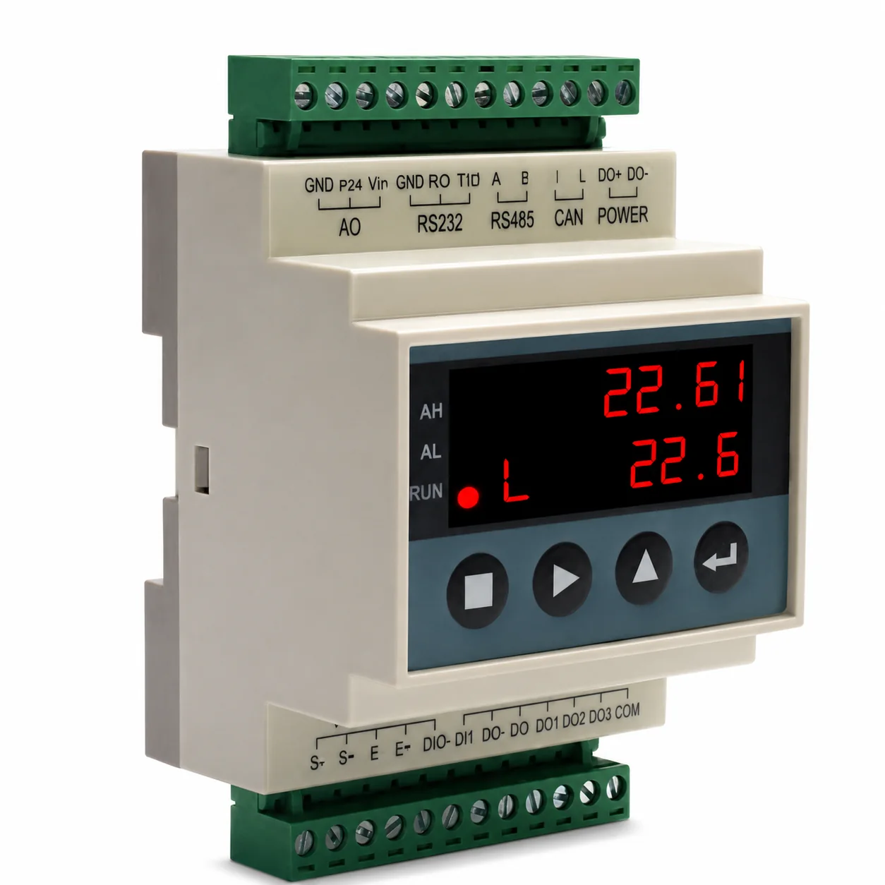
When buyers ask what are the different types of scale indicators, first separate a local display and transaction interface from a signal transmitter, a batching or process controller, and an embedded weighing module. One device may combine roles, but each required function and interface still needs evidence.
- List the operator display, tare, ID and transaction functions
- List analogue, digital, serial and network outputs separately
- Define batching, totalising, alarms and PLC responsibility
- Confirm the load-cell input, enclosure, power and model documentation
Buyer-task questions
Can a transmitter replace an operator indicator?
Only if the project does not require local display, keys, transaction functions or other operator controls that the transmitter lacks.
Can a general indicator control batching?
Not unless the exact model has the required sequencing, setpoints, I/O, fail-safe behaviour and documented program scope.
References
The following official and first-party sources support the bounded examples, standards context and evaluation methods used in this guide. They do not verify an FMSCales configuration.
 Weighing Indicators
 Load Cells
 Truck Scales
 Platform Scales