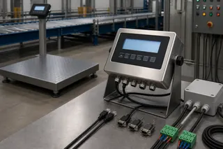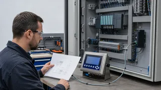
Before rebooting or restoring a weighing indicator, capture the exact display state, model, firmware, option cards, load condition, logs and recent changes. Then isolate one layer at a time and stop when work would require energized access, unsafe machine motion, a broken legal seal or an undocumented configuration change.
“The scale display is broken” can describe a dark screen, a live weight that never settles, a rejected tare, a PLC reading yesterday’s value or a printer that lost only the ticket. Rebooting may clear the symptom while erasing the best clue.
Photograph the display and record the exact model, firmware, option cards, symbols, error code, load state, power condition, process state and recent changes before resetting anything. Then follow the symptom through one layer at a time: supply and hardware, load-cell input, calibration and configuration, operator workflow, I/O, communications, records and peripherals, then environment. Replace or restore the terminal only when a planned test shows that the fault stays with that layer.
Error codes, menu paths, terminals, voltages, password roles, reset functions, firmware files, audit trails and approved repairs differ by model. Follow the current manufacturer manual. Do not open mains-powered equipment, bypass machine interlocks, work in a hazardous area, break a legal seal or make energized measurements unless authorized and qualified. A general-purpose weight output is not automatically a safety function.
If the terminal has not yet been selected, start with the weighing indicator selection guide. Compare evidence-backed candidates in the weighing indicator family; error-code troubleshooting cannot establish model compatibility.
Start from the symptom: a quick orientation table
Match the observed state to the layer most likely to contain the fault. The table narrows the search; it does not replace the layered checks that follow.
| Symptom on the terminal | Most likely layer | First check |
|---|---|---|
| Dark display, no backlight | Power and hardware | Supply voltage, fuse and mains adapter |
| Weight never settles | Physical scale or environment | Mechanical binding, vibration and cable damage |
| Reading frozen or drifting slowly | Sensor signal path | Junction box, connectors and excitation voltage |
| Tare or print refused | Operator function state | Interlocks, motion detection and permissions |
| PLC shows an old or wrong value | Communications contract | Baud and frame settings, register map and scaling |
| Correct weight but wrong record | Records and audit path | Time, identifiers, printer and storage |
One symptom can still have several causes; the layers below isolate them one at a time.
Translate the complaint into a reproducible terminal state
“Indicator broken” can mean the display is dark, the displayed weight is wrong, the operator cannot complete a transaction, a PLC sees stale data, or the printer is unavailable. These have different owners and tests.
Use a symptom statement:
At [time/process state], terminal [exact model/firmware] shows [display/error/status] while the scale is [load/motion state]. The operator/PLC attempts [action], expects [result], receives [actual result], and the issue clears/continues when [condition].
Capture photographs or video of the display, status LEDs, connected scale, and safe external wiring. Export event/service logs and configuration through the documented route. Preserve the failed transaction/message if data is involved. Record whether anyone rebooted, zeroed, tared, calibrated, changed units, restored settings, replaced a sensor, edited PLC code, changed the network, or updated firmware.
METTLER TOLEDO's IND570 user guide, for example, provides model-specific service information and event/error details that can be passed to a service provider.[1] Flintec's FT-111 manual similarly tells users to record problems and displayed error messages before acting on its troubleshooting table.[2] The useful principle is evidence capture; the actual diagnostic screens differ.
Triage by symptom and business consequence
| Symptom | First layer | Immediate business question |
|---|---|---|
| Blank display / resets | Supply, fuse/protection, connector, internal hardware, temperature | Did the device lose accepted records or leave machinery in an undefined state? |
| Stable but wrong weight | Load receptor/cells, configuration, calibration, units/tare | Which prior products or transactions may be affected? |
| Flickering / motion never clears | Mechanical vibration, load-cell signal, noise, filter/motion settings | Is production acting on an invalid live value? |
| Overload / underload / ADC error | Real load, input signal, wiring, excitation, calibration, A/D hardware | Is the structure overloaded or is the input electrically outside range? |
| Zero or tare rejected | Motion, permitted range, mode, permissions, remote command | Is the request appropriate, and would forcing it corrupt a transaction? |
| I/O not switching | Logic state, mapping, option card, wiring, electrical load | Could a gate/feeder move unexpectedly if the signal returns? |
| Serial/Ethernet value missing | Physical link, protocol role, mapping, state, timeout | Is the receiver using last value as if current? |
| Print/store/export failure | Port assignment, media, memory, template, service, permissions | Is the weighing result accepted without an auditable record? |
| Problem after restart/update | Configuration, application, firmware, database, clock | Can the previously approved version be identified and restored? |
If the result controls a commercial transaction, regulatory record, batch release, or safety-significant action, suspend the affected route until the responsible owner evaluates impact. Do not keep operating because the local display “looks close.”
Layer 1: prove power and hardware state
Begin externally. Confirm the specified supply is present under load, protective earth is intact, connector and cable are secure, and the enclosure is within environmental limits. Record low/high-voltage alarms, battery condition, charger, UPS, generator transfer, vehicle cranking, and restart patterns.
Do not replace a fuse until the cause and correct type are known. Repeated fuse failure, smell, heat, burnt marks, liquid ingress, lightning evidence, or damaged mains cable requires isolation and qualified service. Internal service may expose hazardous voltage even after the display is dark.
Observe whether the terminal completes boot, shows manufacturer/application versions, retains time/configuration, and detects option cards. A loop at startup may come from supply collapse, storage/application corruption, option hardware, or an external circuit—not only the main board.
Disconnecting peripherals for isolation can be useful, but follow the manual's power-down and ESD sequence. METTLER TOLEDO's IND570 installation manual requires power removal and a wait before internal electronic connections, and restricts service to qualified personnel.[3] Use the exact warning for the actual product.
If a known-good approved supply or bench setup is used, document it. A stable terminal on the bench does not prove site power, grounding, temperature, vibration, or cables are acceptable.
Layer 2: separate terminal input from the physical scale
A terminal can display a fault caused by the load receptor, cells, junction box, cable, excitation, or its own A/D channel. Inspect the scale mechanically and electrically before recalibrating.
Record excitation, input signal, error range, connector condition, and whether the fault changes when the home-run cable moves. Use the exact wiring guide and safe measurement procedure. For multi-cell systems, check junction-box moisture, channel mapping, and combined bridge load.
A manufacturer-approved load-cell simulator or test source can separate the terminal A/D path from field sensors. If the terminal is stable with a known source, the field system deserves investigation. If the fault remains, input configuration, A/D hardware, power, and terminal environment remain candidates. A simulator does not calibrate the physical scale or prove the structure.
Flintec's DAD 141.1 manual lists model-specific conditions such as input-range, connection, zero-range, motion, overload, and underload messages.[4] The same text on another indicator may use different limits and logic. Always capture the code and consult the right revision.
Do not respond to overload by applying a larger calibration span or suppressing the error. First confirm whether a real mechanical overload exists. A weighing terminal cannot authorize structure capacity.
Layer 3: compare configuration with the commissioned baseline
Configuration faults can mimic hardware failure. Export or photograph current settings before changing them. Compare against the commissioned baseline and approved certificate:
- scale type/channel and load-cell input;
- capacity, divisions, units, decimal, range/interval;
- zero, zero-tracking, tare, motion, stability, filter, and overload settings;
- calibration coefficients, geographic/gravity settings where applicable;
- I/O mapping, setpoints, normal/fail state, delay, latch;
- communication ports, baud/parity, network address, protocol role, registers/messages;
- print templates, record/database configuration, IDs, time/time zone;
- user roles, passwords, seals, audit trail;
- option cards, application package, firmware, and checksums.
Do not perform a factory reset as a diagnostic shortcut. It may erase calibration, application logic, network settings, records, templates, option configuration, and evidence. It may also change legal audit counters or sealing status. Restore only from a verified compatible backup using the manufacturer process and authorization.
A calibration checksum error, setup error, or default-load message requires model-specific recovery. Flintec's FT-111 manual distinguishes several calibration/setup/memory conditions and recommends different actions.[2] Copying one recovery path to another terminal could make it worse.
If a parameter changed, identify who/what changed it: operator, remote command, service software, firmware update, restore, battery/memory failure, PLC, or application. Correct access and change control, not only the value.
Layer 4: test the operator function in its full state
Zero, tare, print, accumulation, recipe, checkweighing or transaction buttons can be rejected because the scale is moving, outside an allowed band, in the wrong mode, under remote command, protected by permissions or waiting for another field.
Observe display annunciators: gross/net, tare, zero, motion/stable, units, range, center-of-zero, overload, active scale, setpoint, network, record, and alarm. Use the model manual to interpret them.
Reproduce the operating sequence with a suitable test load and a clearly marked test transaction. Ask:
- Is the requested function enabled for this role and mode?
- Is weight within permitted zero/tare/print range?
- Has motion cleared under the configured rule?
- Is an ID, product, vehicle, order, or recipe required?
- Does a remote input or PLC command own the action?
- Is the displayed value live, latched, net, gross, peak, total, or previously accepted?
- After power loss, did the application resume an old job?
Do not widen a motion band or zero range merely to make the key work. That can permit unstable or inappropriate results. Investigate vibration, load-cell noise, and workflow first.
Record operator-visible messages and exact steps. If only one user account fails, compare permissions before touching calibration. If all users fail after a configuration deployment, compare the deployed version with the last approved backup and follow the site’s restoration process.
Layer 5: verify I/O without creating machine motion
Digital inputs, relays, transistor outputs, and analogue outputs interact with PLCs, feeders, gates, traffic lights, alarms, and reject devices. Troubleshooting them can move machinery. Put the process into an approved safe test state, isolate actuators where the validated procedure allows, and coordinate with controls/safety owners.
For each point, compare:
- physical terminal and option-card channel;
- electrical type, supply, polarity, common, isolation, and load;
- configured function and scale source;
- normal and fail state;
- trigger condition, hysteresis, delay, latch, acknowledgement;
- PLC tag and inversion;
- observed indicator status, physical voltage/current, and PLC state.
An on-screen setpoint becoming true does not prove relay wiring or the field device. A relay click does not prove the correct gate moved. Test the path end to end with the process in its approved safe test state.
For analogue output, confirm source (gross/net/live/accepted), scaling, units, range, update, isolation, and failure behavior. Measure at the indicator and receiving input using approved instruments. A receiving PLC can apply its own scaling error.
Never use a general indicator relay as a safety-rated interlock unless the complete validated design explicitly supports it. Restoring an output unexpectedly can cause harm; communicate and control the test.
Layer 6: troubleshoot communications as a data contract
Separate physical link, transport/protocol, and application data.
Physical/link
Check cable, connector, pinout, termination, biasing, shielding, isolation, switch port, link LEDs, duplicate address/IP, Wi-Fi/cellular signal, and power. For RS-485, topology and termination matter; random star wiring can fail intermittently.
Protocol/session
Confirm exact protocol/version, serial framing, client/server or master/slave role, address/unit ID, port, timeout, retry, connection limit, and security settings. Capture logs or packets only under authorized cybersecurity policy.
Data semantics
Confirm register/message map, data type, byte/word order, scaling, sign, units, gross/net, live/latched/accepted status, stability, overload/invalid flags, timestamp, and transaction ID. The Modbus Application Protocol defines function codes and data model but not a universal “stable net weight” register for every terminal.[5]
Test failure states: unplug/reconnect, terminal restart, PLC restart, timeout, duplicate message, invalid weight, network loss, and buffer recovery. The receiver must not silently reuse a stale value as current. Compare what the indicator displayed, what it transmitted, what the PLC decoded, and what the business system stored.
Do not change protocol registers or firmware based on an online example. Obtain the exact register map and application revision.
Layer 7: protect records, printers, and auditability
A weight can display correctly while the accepted record is wrong or missing. Trace one transaction end to end:
- operator and identifier entry;
- stable/accepted trigger;
- gross, tare, net, unit, and range;
- time and time zone;
- local storage/database;
- print template and duplicate status;
- export/API acknowledgement;
- correction/cancellation relationship;
- backup and retention.
If printing fails, separate printer power, paper/media, cover/sensor, cable/network, port assignment, driver/protocol, queue, template, character set, and indicator application. Preserve failed jobs before clearing a queue. A test print that omits transaction fields does not prove the production record path.
If memory is full or corrupt, do not delete records until the data owner approves backup and retention. If clock resets, assess all affected timestamps. If a reprint appears identical to an original, investigate duplicate control.
For regulated transactions, follow the approved record and sealing rules. A remote database correction may not be legally equivalent to the original indication or print.
Layer 8: recreate environmental and intermittent faults
Trend faults against temperature, condensation, washdown, sunlight, vibration, vehicle supply, radio use, VFDs, welding, lightning, shift changes, and network load. Inspect enclosure, glands, connectors, vents, fan/filter, printer opening, and mounting.
An IP code does not prove immunity to condensation, chemicals, salt, pressure washing, or a loose gland. A terminal that works after drying still has an ingress problem. Do not heat it or defeat seals; preserve evidence.
Vehicle-mounted indicators may reset during engine cranking or see alternator transients. Outdoor kiosks may overheat in sun. Panel terminals may receive electrical noise or inadequate ventilation. Compare conditions with the exact ratings and installation instructions.
An intermittent problem requires time-correlated evidence. Repeated blind replacement can make the fault disappear temporarily while leaving power, cable, moisture, or grounding untouched.
Substitute one known component without losing traceability
Substitution can isolate a layer when compatible, approved equipment and safe procedure exist:
- known simulator on terminal input;
- known test indicator on field home-run;
- known cable/port/peripheral;
- verified configuration backup on compatible hardware;
- test PLC/client using exact data contract.
Record before/after state and restore it. Confirm calibration and approval implications. A replacement indicator with the same enclosure can have different firmware, input card, excitation, protocol map, application, or certificate scope.
If the fault follows the field signal, continue load-cell, junction-box or mechanical diagnosis. If it stays with the indicator when a compatible known source is connected, escalate terminal service. If it appears only with the PLC or printer, isolate that path. Changing two layers together destroys the evidence gained from substitution.
Recovery and return-to-service gate
Before resuming production:
- Root cause and correction are documented—or an authorized limitation is stated.
- Hardware, connectors, covers, glands, earth, and seals are restored.
- Correct configuration, firmware, option cards, and application are verified.
- Scale zero, span, repeatability, position, and operational tests are completed as applicable.
- Zero/tare/motion/overload behavior is checked.
- I/O is tested end-to-end in safe normal and fault states.
- Communications are tested for value, unit, status, timeout, reconnect, and duplicates.
- Record/print/export reconciliation passes.
- Power interruption and configuration restore are tested where appropriate.
- Legal verification/sealing and safety validation are completed by responsible parties.
- Operators receive any changed instructions.
- As-found/as-left evidence, backup, logs, and open risks are archived.
A successful reboot is not an acceptance test. A correct test weight on the display is not proof that a PLC, print, database, or safety-related action is correct.
Service pack for model-specific help
Provide:
- terminal model, serial, firmware, application, option cards, and manuals;
- scale/cell/junction details and legal/hazardous status;
- exact symptom, display photos, error/event/service logs, and timing;
- configuration backup and comparison with baseline;
- supply measurements and environmental/process correlation;
- load-cell excitation/signal and simulator/substitution results;
- I/O list, measured states, and safe test results;
- protocol map, settings, logs/captures, and sample messages;
- failed/expected transaction and print examples;
- recent hardware, wiring, firmware, PLC, network, or operator changes;
- actions already taken and seal/audit changes.
FMSCales can perform a preliminary document-based comparison of that pack with available model information and identify missing evidence or a possible next isolation question. Exact repair capability, firmware, passwords, spare compatibility, approval, on-site work, and legal service remain unconfirmed until supported by model-level evidence and a written scope.
Stop self-troubleshooting when control is uncertain
Stop for exposed mains/internal service, burnt or lightning-damaged hardware, hazardous-area uncertainty, broken legal seals, safety-related outputs, uncontrolled machine movement, missing manual/backup, unknown firmware/application, corrupted transaction data, or any need to bypass interlocks or cybersecurity controls. Stop if a factory reset, firmware flash, or recalibration is proposed before the as-found state is captured.
The best next step is an evidence pack captured before another reboot. Send the installed-system details through technical support or describe a replacement or redesign through the request-a-quote route. Once the failing layer is isolated, the responsible owner can choose repair, restore, reconfigure, recalibrate, replace or restricted use, then verify the complete measurement and data path before return to service.
Frequently asked questions
Can the previously approved version be identified and restored?
Before rebooting or restoring a weighing indicator, capture the exact display state, model, firmware, option cards, load condition, logs and recent changes. Then isolate one layer at a time and stop when work would require energized access, unsafe machine motion, a broken legal seal or an undocumented configuration change.
References
The following official and first-party sources support the bounded examples, standards context and evaluation methods used in this guide. They do not verify an FMSCales configuration.
- METTLER TOLEDO — IND570 Weighing Terminal User’s Guide
- Flintec — FT-111 Panel Technical Manual, Rev. 2.0.0
- METTLER TOLEDO — IND570 Weighing Terminal Installation Manual
- Flintec — DAD 141.1 Weighing Indicator Technical Manual
- Modbus Application Protocol Specification V1.1b3
- NIST Handbook 44 — Current Edition
 Weighing Indicators