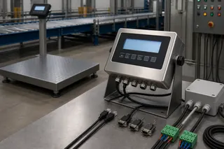
A working Modbus link must carry both the number and the conditions under which that number may be used. Identify the exact indicator and firmware, design the RS-485 segment, turn the register map into a unit-and-status contract, restrict writes, and test normal values, invalid weight states, stale data, timeouts and recovery on the installed PLC.
Suppose the PLC screen shows 12,450 while the indicator shows 12.45 t. Is the link working? Perhaps—but the project still has to establish units, decimal scaling, sign, stability, gross or net state, data age and the response to a disconnected instrument. A useful Modbus connection carries both the number and the conditions under which that number may be used. Put those decisions in a shared, revision-identified interface contract, then test normal readings, invalid states and communication failures on the installed system.
The scope here is Modbus RTU on an RS-485 segment between a weighing indicator and a PLC, HMI or gateway. It is a planning method, not a register map for an FMSCales product or evidence of legal-for-trade suitability. The exact indicator manual and firmware-specific protocol document remain the device authority.
When data looks wrong, locate the layer before rewriting PLC logic
A commissioning call often begins with “Modbus is not working.” That description is too broad to be useful. The fault may sit in the measuring instrument, the cable, the serial framing, the register request or the PLC rule that decides whether to accept a weight. Separate those layers before changing code:
- Measurement layer: load receptor, sensors, indicator, zero, tare, stability, overload, units and valid measurement state.
- Electrical layer: transceivers, conductors, topology, shielding, reference/ground strategy, termination, biasing and electromagnetic environment.
- Serial data-link layer: RTU or ASCII mode, device address, baud rate, parity, stop bits, frame timing and error checking.
- Modbus application layer: function codes, register addresses, exception responses and request/reply behaviour.
- Manufacturer data model: weight field, data type, byte/word order, scale factor, units, status bits, commands and firmware revision.
- Control or business layer: when the PLC accepts a value, what action follows, what record is created and how errors are handled.
The Modbus Application Protocol Specification V1.1b3 describes application-level requests, replies and public function codes. The separate Modbus over Serial Line Guide V1.02 covers serial framing and physical implementation. A quotation that says “RS-485 supported” has not yet confirmed Modbus RTU. One that says “Modbus supported” still leaves the port type, register map and weighing semantics open.
Work downward from the observed symptom. If there is no response, examine electrical and serial identity first. If replies pass CRC checks but the value is implausible, inspect address notation, type, scaling and word order. If the value looks plausible yet the machine acts at the wrong time, examine status, freshness and the PLC acceptance rule. This order saves teams from compensating for one layer’s defect in another layer’s code.
Lock the device identities before anyone writes code
Do not begin with a generic manual downloaded for a product family. Record:
- indicator manufacturer, model and option code;
- serial number or hardware revision where relevant;
- firmware and protocol-map revision;
- installed communication module or port;
- PLC, HMI, gateway or converter model and firmware;
- engineering software and driver/library version;
- topology drawing and cable route;
- intended Modbus role for every node;
- date, revision and source of each technical document.
If a gateway converts RTU to TCP, add its mapping, timeout, retry, connection and address-conversion rules. It is not a transparent wire simply because payload registers appear unchanged. If the indicator documentation uses “master/slave” and newer software uses “client/server,” agree which device sends requests and which answers them rather than relying on terminology alone.
Name one technical owner for the indicator side and another for the PLC side. When firmware, the register map, gateway settings or PLC code changes, repeat the tests that could be affected instead of assuming the interface remains equivalent. Software-based measuring instruments may also be subject to metrological controls. OIML D 31:2008 provides general requirements for software-controlled measuring instruments. It does not prove that a particular installation is approved; it does explain why software identity, protection and recorded authorization of changes matter.
Design the RS-485 segment as an industrial circuit
The Modbus serial-line guide specifies physical-layer implementation considerations, including multipoint arrangements, cable, termination and installation documentation. Follow the exact device manuals and the current project electrical standard rather than copying a bench-test connection into the plant.
Document at least:
- whether the link is a two-wire or other supported arrangement;
- the conductor pair and connector pinout at every device;
- how terminals labelled A/B, D0/D1, +/− or similar are mapped—labels are not sufficiently uniform to guess;
- common/reference conductor requirements from the device manufacturer;
- cable type, impedance where specified, shield and drain treatment;
- segment routing, separation from power conductors and exposure to drives, contactors or welding;
- linear topology, branch/stub lengths and all intermediate connectors;
- termination location and value as required by the approved design;
- biasing/polarization responsibility, ensuring multiple devices do not create an unintended network;
- surge, isolation and grounding approach;
- maximum planned node count and address allocation;
- isolation and lockout steps for installation or service.
Do not troubleshoot by adding terminators or tying grounds until communication appears. That can mask the underlying design and create excessive loading or ground-current problems. Compare the installed segment with the approved drawing, power devices down under the applicable safe-work procedure, and verify conductors and terminations with appropriate test equipment.
A short desk cable may operate despite poor topology, marginal shielding or an incorrect reference. The same design can fail when extended beside a variable-frequency drive or connected between separately grounded panels. Acceptance must therefore occur on the final cable route with the actual devices energized and the relevant machinery operating, not only on a workbench.
Establish serial settings and server identity
For every server device, record the address, transmission mode, baud rate, parity and stop-bit settings. Do not use “default” in the contract; defaults can change after replacement, reset or firmware update. Create and retain an address schedule for a multidrop segment.
The commissioning procedure should verify:
- The PLC or client uses the intended serial port and electrical mode.
- Every server has a unique permitted address.
- All devices share compatible serial formatting.
- Request timeouts allow the stated device response behaviour.
- Polling and retries do not saturate the segment.
- Exception responses, CRC errors and timeouts are counted separately.
- A disconnected or silent device becomes an explicit invalid state rather than leaving a believable old value.
Use a serial analyzer or diagnostic client when appropriate, but preserve the final PLC test. A laptop tool that reads registers proves only its own configuration and requests. It does not prove that the PLC program interprets the data correctly or handles failures safely.
A first-connection example the site can test
Many projects begin from the same default profile. Treat the values below as a starting point to confirm against the exact model manual, not as guaranteed settings:
| Parameter | Typical starting value | What to confirm |
|---|---|---|
| Baud rate and frame | 9600 bps, 8 data bits, no parity, 1 stop bit (8N1) | Both ends must match exactly; 19200 bps is the common alternative |
| Server address | 1 | Change it when several indicators share the segment |
| Weight register | Holding register 40001, read with function 03 | Some models map weight to 30001 (function 04) or to a scaled register pair |
| Data format | 16-bit integer with documented scaling | 32-bit float or double-register values need the word order agreed |
| Line termination | 120 ohm resistor at both ends of the segment | Add bias resistors when the master does not provide them |
A first poll that returns a plausible weight with the documented scaling proves the physical layer, the address and the register map in one step.
Turn the register map into a contract the site can test
A register table can produce the first successful read and still leave the project unable to accept the result. Expand it into a project table with one row for every value or command the PLC will actually use:
| Contract field | What must be written down |
|---|---|
| Business name | Gross weight, net weight, stable accepted weight, total, status, command, etc. |
| Device reference | Exact register/table name and firmware-map revision |
| Modbus address | Address as entered in the client, noting whether documentation uses zero- or one-based notation |
| Function code | Read/write operation the server supports |
| Width and type | Bits/registers; signed or unsigned integer, floating point, text or packed status |
| Byte/word order | Exact arrangement for multi-register values |
| Scale and units | Raw count conversion, decimal position and engineering unit |
| Validity | Status bits and conditions required before use |
| Update behaviour | Rate, latching, transaction trigger or change behaviour |
| Failure value | Timeout, exception, sentinel, stale-state and quality handling |
| Write control | Permission, interlock, acknowledgement and audit requirement |
| Test case | Known stimulus and expected raw and engineering result |
Address notation causes frequent commissioning delays. Modbus data models describe coils, discrete inputs, input registers and holding registers, but human documentation may present references differently from the numeric address a client library expects. Do not solve an address offset by trial and then leave it undocumented. Record the source notation and the actual client call.
Multi-register values create another ambiguity. The Modbus protocol defines how bytes are transmitted within a 16-bit register, but device vendors may arrange the words of a 32-bit or larger value differently. Confirm with the exact manual and a known test value. Do not assume that the PLC’s default floating-point conversion matches the indicator.
Define what a “weight” means
The validity rule deserves more attention than the address. A scale may expose gross, net, tare, filtered display weight, raw measurement, peak, accumulated total or a completed transaction. Each can be a legitimate value while remaining unsuitable for the PLC task.
Ask these questions:
- Is the value gross or net? Which tare source is active?
- Is it the instantaneous internal value, the displayed value or a captured stable value?
- What unit and decimal interpretation apply?
- Which bit indicates stability or motion?
- How are overload, underload, negative, centre-zero, sensor fault and calibration mode represented?
- Does a status register apply to the same update instant as the weight register?
- Can a multi-register value change between separate requests?
- Does the value remain at its last reading after the instrument becomes invalid?
- Is a zero value a real measurement, an initialization state or a communication substitute?
- What event converts a live value into a completed record?
The PLC should not treat “communication healthy” as “measurement valid.” Build a quality state that combines successful response, freshness, device status, permitted operating mode and any application-specific stability requirement. When the state is invalid, inhibit or qualify downstream action according to the risk assessment; do not silently reuse the last value.
For regulated or commercial measurements, confirm whether remote indication, printing, transmitted values, software and commands fall within the approved complete instrument and local verification. A Modbus read that numerically matches the display is not itself evidence of approval for a transaction.
Distinguish live process values from completed records
A PLC may need a rapidly refreshed value for process awareness. An ERP needs a durable business record. These are different interfaces.
A completed record normally requires a trigger and identity: transaction ID, material or product, vehicle or load ID, gross/net/tare context, unit, time, operator or system, scale/device identity, quality/status and acknowledgement. Decide which system creates the authoritative ID and which system owns correction. If a gateway or PLC retries after a network failure, the destination must recognize the same transaction rather than creating a second one.
The OPC UA for Weighing Technology companion specification, OPC 40200 v2.00 illustrates the value of a defined weighing information model, states and scale types. A project does not need to adopt OPC UA to learn from that principle: name the object and state being exchanged. A folder of anonymous Modbus registers is not a business data model until the project defines their relationships.
Keep the existing weighing system data integration guide as the owner of ERP/WMS transaction architecture. Use this page for the serial device contract and fault tests.
Restrict and engineer write commands
Reading weight is usually lower risk than writing zero, tare, setpoint, recipe, calibration or configuration values. Do not enable writes because a register exists.
For each permitted command, document:
- operational purpose and authorized role;
- preconditions, including machine and measurement state;
- exact value and function code;
- momentary, edge-triggered, latched or level behaviour;
- positive acknowledgement and post-condition;
- timeout and retry rule;
- duplicate-command consequence;
- local/remote mode interaction;
- audit log requirement;
- recovery after PLC, indicator or network restart;
- safety and legal-metrology restriction.
Never retry a non-idempotent command blindly. A timeout means the response was not received; it does not prove the server failed to execute the request. The client may need to read the resulting state before deciding whether another write is safe.
Calibration and legally protected configuration deserve an explicit prohibition unless the complete approved workflow supports remote operation. Keep commissioning convenience separate from operational authority.
Set polling, freshness and load deliberately
Fast polling does not improve the underlying measurement and may reduce network reliability. Calculate a practical schedule from the number of devices, requested registers, response time, baud rate, PLC scan and required decision latency. Group contiguous reads only when the device documentation permits it and the values form a coherent snapshot.
Define:
- normal poll interval by data class;
- maximum acceptable age for control and display;
- response timeout and retry count;
- backoff or degraded polling after repeated failure;
- diagnostic counters and alarm thresholds;
- recovery sequence after communication returns;
- whether re-synchronization or a fresh stable event is required.
Store a timestamp or PLC scan time with the quality state. A cached number without age can remain plausible long after a cable is removed. Test this condition deliberately.
Include OT cybersecurity and maintenance ownership
An RS-485 segment is not automatically secure because it is not Ethernet. Physical access, gateways, maintenance laptops, protocol converters and remote support can create paths into operational technology. NIST SP 800-82 Rev. 3 provides current guidance for OT security while accounting for performance, reliability and safety.
The project should identify:
- physical and network boundaries;
- who can change device address, serial settings or register permissions;
- configuration backup and restoration ownership;
- approved engineering tools and portable media;
- gateway account, certificate and remote-access controls;
- logging and change records;
- replacement and firmware-update procedure;
- fail-safe behaviour during cyber or communication incidents.
Do not expose a serial gateway directly to an untrusted network. If Modbus TCP or remote access is added, perform a separate security design rather than assuming the serial protocol provides authentication or confidentiality.
Run a fault-inclusive site acceptance test
The final test should use the installed network and actual PLC code. Include at least these categories:
Data representation
- zero, positive and any permitted negative values;
- values that reveal decimal scaling and multi-word order;
- gross, net and tare transitions;
- every required unit and range;
- status bits matched to the same operating condition.
Measurement states
- stable and moving load;
- overload/underload or other documented invalid states;
- zeroing or tare operation;
- permitted local and remote modes;
- instrument startup and configuration mode.
Communication faults
- open conductor or powered-off server;
- wrong server address or serial setting;
- CRC/exception response where testable;
- gateway restart and PLC restart;
- delayed response and stale data;
- duplicate address on an isolated test segment.
Business and control behaviour
- accepted transaction with all fields;
- repeated request and duplicate prevention;
- power loss before and after acknowledgement;
- downstream system unavailable and later recovery;
- unauthorized or unsafe write request rejected;
- backup restoration followed by version verification.
Record raw request/response evidence where practical, PLC engineering values, device display/state, expected result, actual result and pass/fail decision. Save the register contract, code version, device configuration and acceptance evidence together.
What the buyer should send for an interface review
Before requesting a quotation, supply:
- Exact indicator and communication option, or the required device behaviour if selection is open.
- Register map with its document revision and matching firmware, when available.
- PLC/gateway model, software version and intended client/server roles.
- RS-485 topology and cable-route drawing.
- Required live values, completed records, status and commands.
- Unit, scaling, timing, freshness and invalid-state rules.
- Control consequences and safety interlocks.
- OT network, remote access and change-control policy.
- Acceptance cases, evidence and responsible parties.
Attach these items to the request-a-quote form and reference the weighing data integration solution. A responsible response should identify supported functions for the exact proposed model and version, document exceptions, and separate device configuration from PLC, gateway and enterprise-system work.
Define the data contract before wiring
A reliable approach to interfacing a platform scale to a plc requires more than matching an RS-485 terminal. Confirm the exact protocol, physical layer, node settings, register map, data type, byte order, units, stability and error flags, write permissions and timeout behaviour for the selected indicator.
- Obtain the current model manual and register map
- Agree address, baud rate, parity, data type and byte order
- Define valid, unstable, overload, negative and communication-fault handling
- Test with recorded request and response frames before production control
Buyer-task questions
Is RS-485 the same as Modbus RTU?
No. RS-485 defines an electrical layer; Modbus RTU is one protocol that may use it. The device manual must confirm the actual protocol.
Should a PLC write tare or zero commands automatically?
Only after authority, operating sequence, interlocks, audit requirements and failure behaviour are explicitly reviewed for the application.
References
The following official and first-party sources support the bounded examples, standards context and evaluation methods used in this guide. They do not verify an FMSCales configuration.
- Modbus Application Protocol Specification V1.1b3
- Modbus over Serial Line Specification and Implementation Guide V1.02
- Modbus Organization — Specifications and Implementation Guides
- NIST SP 800-82 Rev. 3 — Guide to Operational Technology Security
- OIML D 31:2008 — Software-controlled Measuring Instruments
- OPC 40200 — OPC UA for Weighing Technology
 Weighing Indicators
 Load Cells
 Truck Scales
 Platform Scales