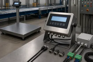
A belt scale combines the measured load carried over the weighing zone with belt speed to calculate mass flow, then integrates that flow over time to produce a total. The result depends on the complete mechanical, sensing, integration and data chain—not on the load cells or display alone.
Suppose two suppliers quote a belt scale for the same 1,000 mm conveyor. One asks for idler spacing, take-up position, speed range, and minimum flow; the other offers an accuracy percentage from the belt width alone. The first supplier is asking the questions that determine whether the sensors will see a representative load. Belt width by itself cannot answer that.
The underlying calculation uses two inputs: material load per unit length of belt and actual belt travel speed. A weigh frame transfers force from selected conveyor idlers to load cells. A speed sensor represents belt movement. The integrator filters and combines the two signals into an instantaneous mass-flow rate, then accumulates that rate over time. Conveyor alignment, tension, loading profile, zero, calibration, and operator practice all affect the result because they influence one of those inputs or how the total is accepted.
Understanding that chain makes quotations easier to compare. Buyers can ask where load and speed are measured, what conditions can disturb them, and whether the required output is a live rate, an accumulated total, or an accepted production record. The discussion here is limited to continuous belt-conveyor scales. Weighfeeders that actively regulate feed, nuclear or optical flow measurement, truck scales, and batch scales use different measurement arrangements. OIML R 50-1 defines the conveyor-belt type of continuous totalizing automatic weighing instrument under national metrological control; regulated use still depends on the precise approval and local law.
The complete chain in one line
At concept level:
mass flow rate = material loading on the belt × belt speed
and:
total mass = accumulated mass flow over elapsed time
The units must agree. If loading is expressed as kilograms per metre and speed as metres per second, their product is kilograms per second. The integrator may display another engineering unit, average the signal, apply configured factors and totalize in tonnes, but those transformations must remain documented.
The equation is simple. Producing trustworthy inputs is the engineering task.
1. The conveyor carries both useful load and unwanted influence
Material passes over a group of idlers. Within the weighing zone, one or more idlers are mechanically connected to a weigh frame so that a defined portion of vertical force reaches the load cells. The system must distinguish the material contribution from the belt, idler, structure and other dead-load effects. The empty running conveyor therefore establishes a zero baseline.
The load cell does not “know” which force came from product. It responds to the load path presented to it. Misaligned idlers, belt tension effects, material build-up, mechanical binding, a cable pulling on the frame or a distorted stringer can change that path. This is why installed-system performance cannot be inferred from a component datasheet.
The weigh frame also has a finite influence or weigh length determined by the design and idler arrangement. Ask the supplier to identify the scale idlers, approach and retreat idlers, effective weigh length, and minimum loading conditions for the proposed model. A generic diagram cannot supply those values for an unknown frame.
2. The speed sensor must represent actual belt travel
The speed input converts movement into distance or velocity. Depending on the system, the sensor may be driven by a pulley, return roller, wheel or another approved mechanism. Its location matters. Slip, material build-up, poor contact, an incorrect pulley circumference or a configuration mismatch can bias the flow value even when the weigh frame responds correctly.
Thermo Fisher describes belt-speed sensors that generate pulses proportional to belt travel, while its system explanation identifies the weigh carriage, speed sensor and integrator as the principal measurement elements. That is a useful architecture example, but buyers must confirm the actual sensor route for the quoted system. “Digital speed sensor” says nothing about whether it represents true belt movement under the project’s conditions.
Variable-speed conveyors make this especially visible. If belt load remains constant but speed doubles, mass flow doubles. If the integrator receives a fixed nominal speed instead of the actual changing speed, the total becomes wrong by design. Conversely, a stable speed signal cannot correct a biased load signal.
3. The integrator turns signals into meaning
The integrator receives conditioned load and speed inputs. It applies configuration values, zero and span factors, filters or damping, validity rules and unit conversions. It calculates rate, accumulates total and may expose alarms, analogue outputs, pulses, fieldbus registers, network data, printed records or operator functions.
Those outputs serve different tasks:
| Output | Typical consumer | Question the buyer must answer |
|---|---|---|
| Live load signal | Commissioning or diagnostics | Is this raw, filtered or engineering-unit data? |
| Belt speed | Operator, PLC or diagnostic logic | Where is it measured, and how is invalid speed shown? |
| Instantaneous flow rate | Process operator / PLC | What filtering and update rate apply? |
| Totalizer | Production or inventory team | Who can reset it, and what happens at rollover or power loss? |
| Alarm/status | Operator / maintenance | Does the receiving system distinguish bad data from zero flow? |
| Completed production record | MES, ERP or report | Which system adds material, batch, shift and acceptance context? |
A live rate and a completed transaction answer different questions. The PLC may read tonnes per hour every second, while the production system needs one accepted shift total with site, conveyor, material, start/end time, configuration status, and exception notes. The integrator supplies measurement data; the business record may need fields owned elsewhere.
What happens during zero, span and material calibration
An empty belt still loads the weighing mechanism. Zero calibration observes the empty running system and establishes the baseline against which product is measured. The observation must cover enough belt travel to represent belt variations, using the exact rule in the manufacturer’s instructions. A stopped-belt “zero” cannot reveal the same dynamic pattern.
Span calibration applies a known or simulated load according to the system’s approved method. The device may be a test weight, chain or electronic simulator. Span demonstrates response to that input and is essential for commissioning and routine control, but the coverage differs by method. An electronic simulation may exercise electronics without loading the mechanics; a static weight exercises a defined mechanical route but not real material distribution.
A material test moves a quantity of product whose value is independently determined by a control method. It therefore tests more of the installed chain. OIML R 50 explicitly defines control methods and the control instrument used to establish the test-load value. Siemens’ manufacturer instructions for a specific weighfeeder recommend material tests for maximum accuracy. Neither statement means every site can use the same test quantity, sequence or tolerance. Those remain model-, application- and jurisdiction-specific.
The separate belt scale calibration procedure owns the executable test plan. This explainer’s role is to show why each test answers a different question.
Why conveyor mechanics become measurement inputs
A belt scale is installed inside a material-handling machine, not on an isolated laboratory bench. The conveyor structure and operating state therefore matter.
Idler alignment and support
The scale idler and neighboring idlers establish how the belt crosses the weighing zone. Height, squareness, spacing, roll condition and frame stiffness affect force transfer. Siemens’ MSI/MMI instructions give precise placement and alignment requirements for those models. A project should use that model-specific document, then preserve an installation record for future maintenance.
Belt tension and take-up behavior
The belt must conform to the idler profile while carrying material. Changing tension, take-up movement, belt stiffness, splice behavior or tracking can alter forces at the weigh frame. A location close to major conveyor disturbances can make those effects harder to control. The supplier should review take-up type and distance, inclination, curves, loading points and transition geometry before naming a location.
Material loading profile
The totalizer only measures material that crosses the active zone under conditions within the system’s intended range. Very light, intermittent, off-center or surging loading may produce a different uncertainty than steady, centered loading. The design flow rate alone is insufficient: provide minimum, normal and maximum actual flow, bulk-material behavior and expected speed range.
Environment and housekeeping
Dust, carryback, water, temperature, vibration and falling material can change zero, damage cables or restrict motion. Housekeeping is measurement control when accumulation touches the weigh frame or adds dead load. Protection must not create another mechanical contact or make inspection unsafe.
Four values buyers should not confuse
Display resolution is the smallest indicated step. It does not equal accuracy.
Repeatability describes how closely results agree when the same procedure is repeated under controlled conditions. Repeatable bias can still be wrong.
Error against a reference compares an indicated or totalized result with a suitable control value for a defined test.
Uncertainty describes doubt around a result, including contributions from reference, method, environment and repeatability. A simple brochure percentage rarely contains enough information to compare uncertainty across systems.
Ask every bidder to state performance with the conditions: flow range, belt loading, speed, material, conveyor geometry, calibration method, test duration, reference method and whether the value is typical, guaranteed, approved or site-accepted. OIML R 50 provides accuracy classes and requirements for instruments within its scope; NIST Handbook 44 provides U.S. model requirements where adopted. A vendor’s value under one framework should not be copied into another project without checking scope.
Accuracy classes and the weigh-frame structures behind them
Quoted belt-scale accuracy usually describes a structure class rather than a single component. The figures below show what each class typically requires and where it is used:
| Accuracy class | Typical weigh frame | Typical use |
|---|---|---|
| ±0.25 % | Multi-idler frame with four or more weigh idlers | Custody transfer, ship loading and high-value materials |
| ±0.5 % | Dual-idler frame on a well-aligned conveyor | Plant inventory and production accounting |
| ±1 % | Single-idler frame | Process indication and trend monitoring |
A class is achievable only when the conveyor condition, alignment, speed measurement and calibration practice support it. A multi-idler frame on a poor conveyor performs worse than a single-idler frame on a good one.
A worked example without invented product numbers
Imagine a process conveyor where the belt-scale integrator shows a stable rate and accumulating total, but the daily receiving record is consistently higher. Do not immediately change span.
Trace the chain:
- Confirm both systems use the same period, material boundary and units.
- Check whether either totalizer was reset, rolled over or continued through downtime.
- Review zero history and inspect for build-up or mechanical contact.
- Confirm belt-speed representation and configured circumference or pulses.
- Check material diversion, spillage, recirculation and inventory timing.
- Perform authorized zero and span checks.
- If justified, conduct a controlled material test against a suitable reference.
- Adjust only after identifying a valid measurement bias.
This sequence protects the buyer from “calibrating” a reporting-window mismatch or a mass-balance boundary error into the instrument.
How the principle changes the RFQ
Once the measurement chain is understood, a useful RFQ becomes specific. Include:
- conveyor drawing, width, inclination, stringer and idler details;
- take-up type and proposed distance from disturbances;
- belt construction, speed range and whether speed varies;
- material, bulk behavior and minimum/normal/maximum flow;
- required rate, total, reset, alarm and record behavior;
- purpose: monitoring, control, inventory, transaction or another defined task;
- available shutdown and safe service access;
- desired calibration methods and available control instrument;
- environmental conditions and cleaning practice;
- PLC, analogue, pulse, fieldbus or network interface needs;
- destination country and any regulated-use requirement;
- acceptance test, records, training and spare-parts expectations.
Replace the bare question “What accuracy can you supply?” with a more useful request: mark the proposed weigh zone, explain both measured inputs, identify invalid-data behavior, provide the calibration route, and state the conditions behind every performance claim.
Boundaries that protect the project
A belt scale total should not be used to authorize conveyor overload. The conveyor manufacturer’s limits and site safety controls remain separate. Installation and maintenance near moving belts require the applicable guarding, isolation and hazardous-energy procedures. OSHA’s lockout/tagout standard is one U.S. example; mining operations and other jurisdictions may have additional rules.
Likewise, a component certificate does not approve the whole installation. Legal-metrology status can depend on the exact instrument, software, scale location, markings, seals, test method and local verification. Keep the intended-use statement visible in the purchase specification.
Data integration has its own boundary. ISO/TS 15143-3 defines a telematics data schema for certain mobile machinery server-to-customer interfaces, but its scope does not define onboard payload measurement. It is an instructive reminder that a data standard can describe transport without proving how a value was generated. For belt scales, an interface logo similarly does not establish update behavior, field ownership or measurement validity.
Move from understanding to a reviewable configuration
If your project is still choosing the weighing zone, use the belt scale selection guide to document conveyor geometry, loading range and calibration access. Review the belt scale family for available configuration routes. If the system is installed, move to the belt scale calibration procedure and build the evidence package.
To request a review, send FMSCales the conveyor drawing, idler and belt data, speed and flow ranges, material, operating purpose, proposed location, output requirements, control system and destination country through the project inquiry form. The response should identify missing inputs and a quotation route; it must not be treated as final approval of the conveyor, installation or regulated use.
Follow the complete signal chain
A belt scale converts supported belt load and measured belt movement into instantaneous flow and accumulated total. The result depends on the weigh zone, idlers, load sensing, speed sensing, integrator configuration, belt condition and the checks used to maintain the system.
- Load sensing estimates material carried through the weigh zone
- Speed sensing represents belt movement over the same measurement interval
- The integrator combines the inputs into flow and total values
- Zero, span and material checks test different parts of the installed chain
Buyer-task questions
Does the integrator determine accuracy by itself?
No. It processes the signals, but the installed result also depends on the conveyor, idlers, belt, load and speed sensors, wiring, configuration and calibration method.
Why does belt loading profile matter?
Uneven or very light loading can change the signal-to-noise conditions and how well the weigh zone represents the material flow.
References
The following official and first-party sources support the bounded examples, standards context and evaluation methods used in this guide. They do not verify an FMSCales configuration.
- OIML R 50-1:2014 — Continuous totalizing automatic weighing instruments, reconfirmed 2024
- NIST Handbook 44 — Current Edition
- Thermo Fisher Scientific — Belt Scale Selection and Technology Guide
- Thermo Fisher Scientific — Belt Conveyor Scale Handbook
- Siemens — Milltronics MSI and MMI Operating Instructions
- Siemens — SITRANS WW200 Operating Instructions
- ISO/TS 15143-3:2020 — Worksite data exchange, Part 3
- OSHA 29 CFR 1910.147 — Control of Hazardous Energy
 Belt Scales