
Survey the conveyor before selecting a belt scale. The weigh frame, speed sensing, integrator, idlers, belt tension, material profile and calibration method form one measurement chain. A strong quotation states the required site data and the conditions under which performance will be tested.
1. Survey the proposed weighing zone
Look for a straight, stable section with uniform belt support and enough distance from loading points, curves, trippers, take-ups and other disturbances. Record what cannot be changed before the supplier proposes a frame.
- Conveyor inclination and structural condition
- Idler type, spacing and alignment
- Belt construction, tension and tracking
- Distance from feed and discharge disturbances
- Space for installation and safe service access
2. Define the real operating range
Give normal, minimum and maximum flow—not only design capacity. Include belt speed variation, material density and the expected loading profile. Very light loading may need a different system or longer averaging than peak production.
3. Treat speed sensing as a measured input
A belt scale calculates flow from load and belt movement. Specify where speed is measured, how slip is avoided and how the signal is checked.
| System element | Selection question | Handover evidence |
|---|---|---|
| Weigh frame | Is the structure suitable for the idler and load range? | Installation dimensions and alignment record |
| Speed sensor | Does it represent actual belt movement? | Mounting and signal check |
| Integrator | Which totals, alarms and outputs are needed? | Configuration backup and I/O list |
| Calibration | Can material tests or a suitable simulator be used? | Procedure, reference and result |
4. Plan zero, span and material checks
Define who performs routine zero checks, what calibration equipment is available and when a material test is practical. A calibration plan that cannot be executed at the site is not a plan.
5. Specify interfaces and failure behaviour
Document pulses, analogue outputs, fieldbus or network data, tag names and what the process control system should do if weight or speed data becomes invalid.
Decision guidance
For process trending, availability and maintainability may be the primary criteria. For inventory accounting or regulated use, define tighter evidence, test and approval requirements before choosing the system.
A component specification does not guarantee installed-system performance. Local legal-metrology requirements and the exact model must be confirmed for trade use.
Frequently asked questions
Is the structure suitable for the idler and load range?
Look for a straight, stable section with uniform belt support and enough distance from loading points, curves, trippers, take-ups and other disturbances. Record what cannot be changed before the supplier proposes a frame.
References
The following official and first-party sources support the bounded examples, standards context and evaluation methods used in this guide. They do not verify an FMSCales configuration.
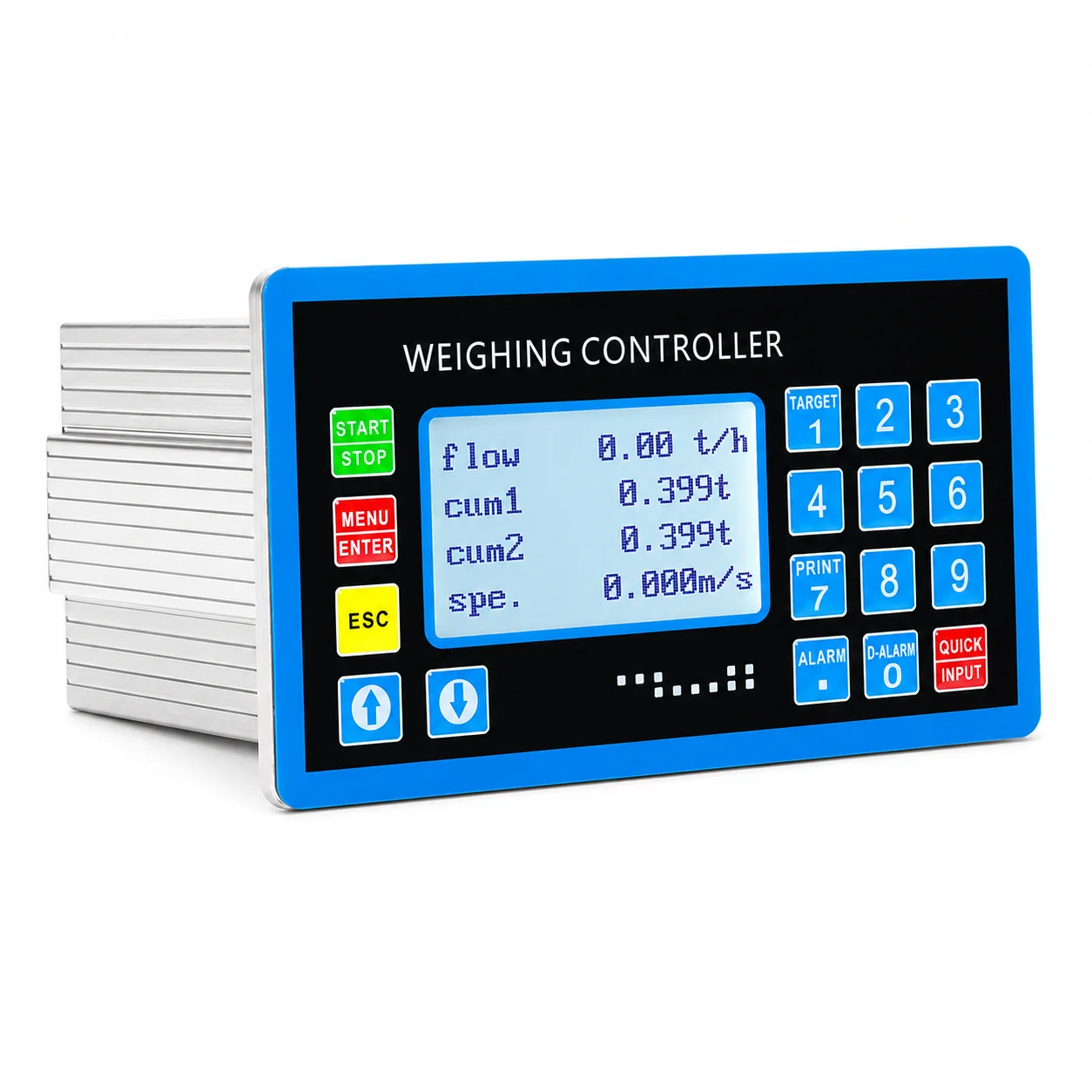 Belt Scales
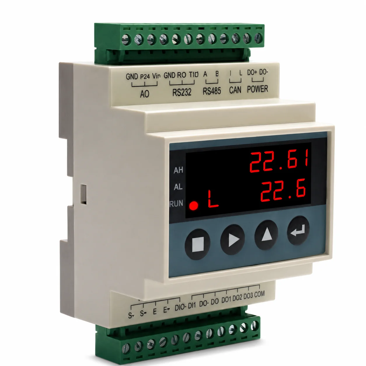 Weighing Indicators
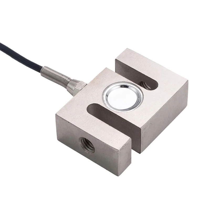 Load Cells
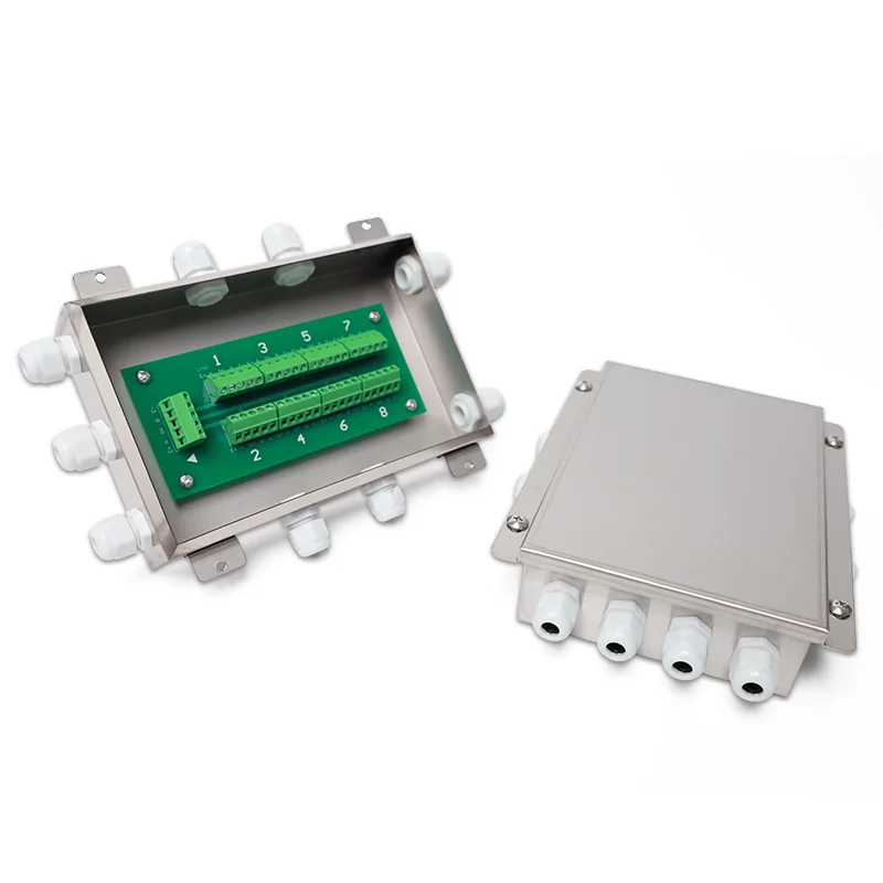 Load Cell Accessories