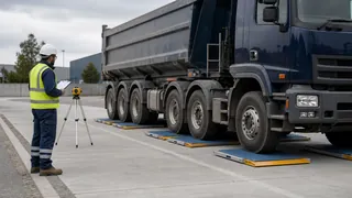
Treat wheel loader scale accuracy as the result of a controlled weighing cycle, not a fixed property of the indicator. Warm the machine, use the defined lift window, keep the loader within the agreed slope and speed limits, and verify with suitable reference loads under representative site conditions.
1. Control the machine state
Hydraulic oil temperature, mechanical wear, tyre condition and attachment geometry can change the relationship between pressure, position and payload. Define a warm-up and daily inspection routine instead of recalibrating around an unstable machine.
- Complete the prescribed warm-up
- Inspect pins, hoses and attachment play
- Use the configured bucket or attachment
- Confirm sensors and cables are undamaged
2. Make the lift cycle repeatable
Use the same lifting direction, speed range and measurement window for every accepted weighing. Avoid steering, braking or abrupt hydraulic movements during the measurement window.
| Variable | Why it matters | Operating control |
|---|---|---|
| Lift speed | Changes the dynamic hydraulic response | Define an acceptable speed window |
| Slope | Changes load distribution and machine attitude | Set site limits and test on representative ground |
| Bucket position | Changes geometry and load path | Use the configured rollback position |
| Material movement | Creates an unstable load | Allow the load to settle before the weighing window |
3. Separate calibration from verification
Calibration establishes the system response. Verification checks whether that response remains acceptable. Record the reference load, date, conditions, operator and result so a drift investigation has evidence.
4. Diagnose drift before adjusting
When results move, check machine condition, sensor mounting, connectors, lift behaviour and reference-load reliability before changing calibration. An adjustment made to compensate for a mechanical problem can hide the cause.
5. Agree the commissioning record
The handover should identify the configured machine and attachment, test method, operating boundaries, user access, calibration responsibility and maintenance interval.
6. Recalibrate only after a defined trigger
Calibration is not a routine consumable. Recalibrate when a defined event changes the measurement chain, and verify first when the change is only suspected. A trigger list agreed at handover keeps the decision consistent between operators and service visits.
- Attachment changed, repaired or re-pinned
- Hydraulic pump, valve or cylinder work completed
- Weighing sensor, cable or connector replaced
- Seasonal temperature shift beyond the agreed operating band
- Verification against the reference load confirms drift beyond the agreed limit
7. Know the accuracy bands buyers actually quote
Field accuracy is agreed per application, not read from a brochure. The bands below reflect what buyers and suppliers typically write into commissioning records for a correctly installed onboard loader weighing system operating inside its defined limits.
| Intended use | Typical field band | What supports it |
|---|---|---|
| Process guidance and overload avoidance | ±1–2% of payload | Standard onboard system with a controlled lift cycle |
| Inventory and production records | ±0.5–1% of payload | Defined lift window plus weekly verification against a reference load |
| Dispatch or transactional use | ±0.5% of payload or better | Approved instrument configuration where the jurisdiction requires legal-for-trade use |
8. Budget the error before blaming the scale
A repeatable weighing cycle keeps every contributor small. When results drift, quantify each source in this order before touching calibration.
| Error source | Typical contribution | Primary control |
|---|---|---|
| Machine and hydraulic condition | The largest single variable in most field reviews | Warm-up routine and scheduled maintenance |
| Lift cycle variation | Noticeable scatter when speed or slope leaves the agreed window | Speed window, site slope limits and one written sequence |
| Attachment and load path | A systematic offset after bucket or pin changes | Configured rollback position and trigger-based recalibration |
| Reference load quality | Unknown unless the reference itself is verified | Certified test weights or a verified weighbridge |
| Operator sequence | Random scatter between shifts | One trained sequence with the same window for every lift |
9. Run a one-shift field verification
A compact protocol the site can repeat without special equipment beyond a known reference load. Record every result with the machine, attachment, operator and conditions.
| Step | Action | Pass criterion |
|---|---|---|
| 1. Warm-up | Operate the hydraulics 15–20 minutes to reach working temperature | Oil and machine at normal operating state |
| 2. Zero check | Three empty-bucket lifts through the defined window | Zero return inside the indicator tolerance |
| 3. Span check | Five lifts with a reference load near the typical payload | Mean error inside the agreed band for the intended use |
| 4. Repeatability | Five more lifts with the same load and sequence | Spread between highest and lowest inside the agreed limit |
| 5. Record | File date, machine, attachment, loads, results and operator | Verification evidence attached to the commissioning record |
Decision guidance
Choose a loader scale only after the supplier has reviewed machine and hydraulic data and can describe the commissioning test. If the buyer cannot standardise the lift cycle, use the weight as process guidance rather than an unsupported transactional value.
Field performance varies with installation and operating conditions. A load-cell or indicator specification alone does not establish the accuracy of the complete loader weighing system.
References
The following official and first-party sources support the bounded examples, standards context and evaluation methods used in this guide. They do not verify an FMSCales configuration.
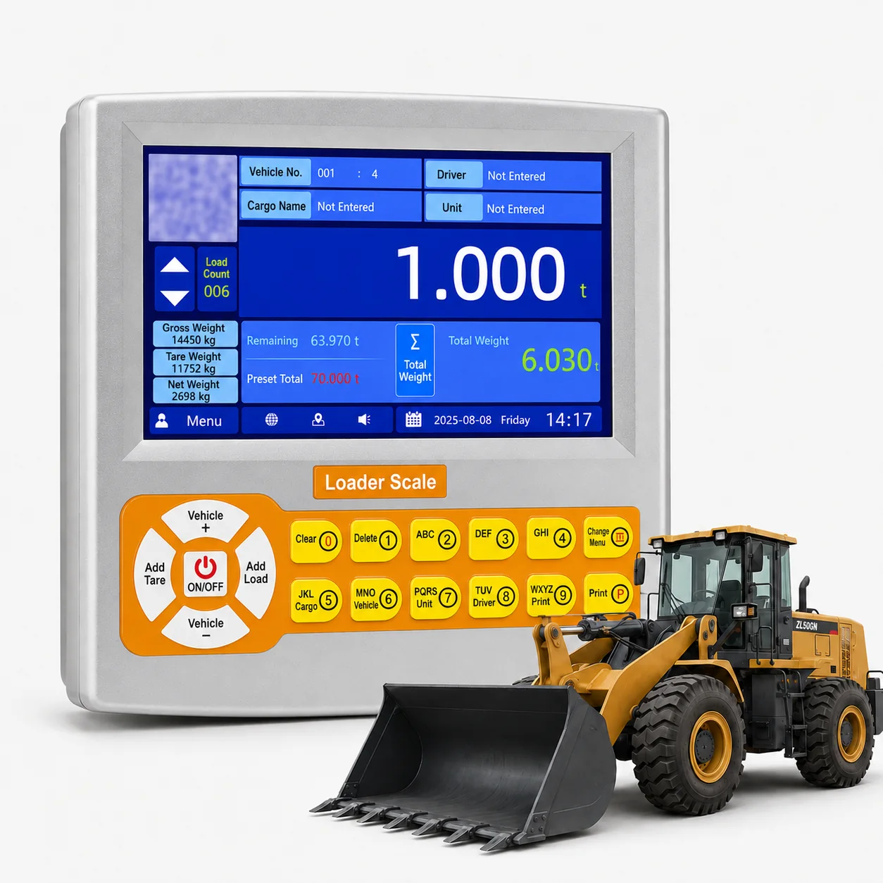 Loader Scales
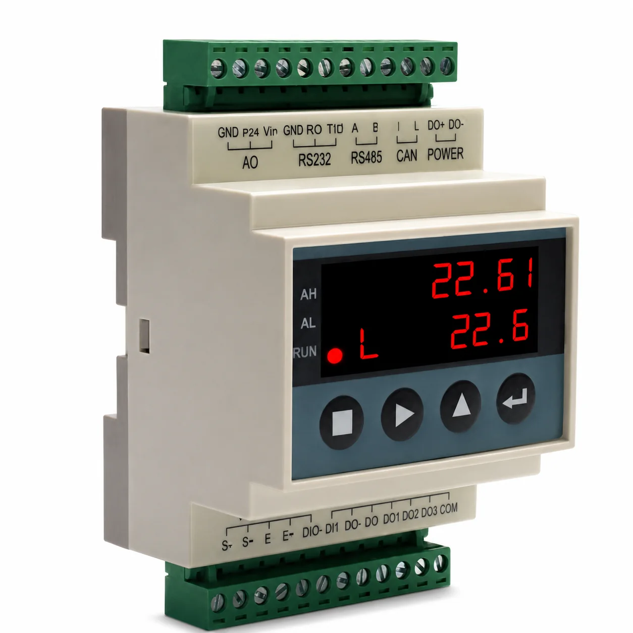 Weighing Indicators
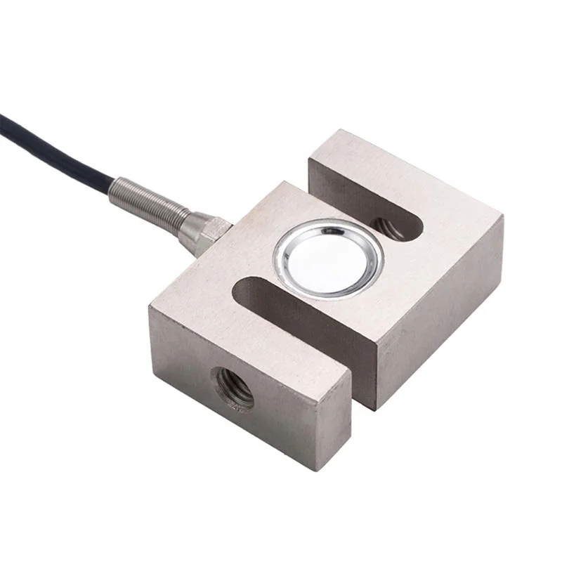 Load Cells
 Excavator Weighing Systems