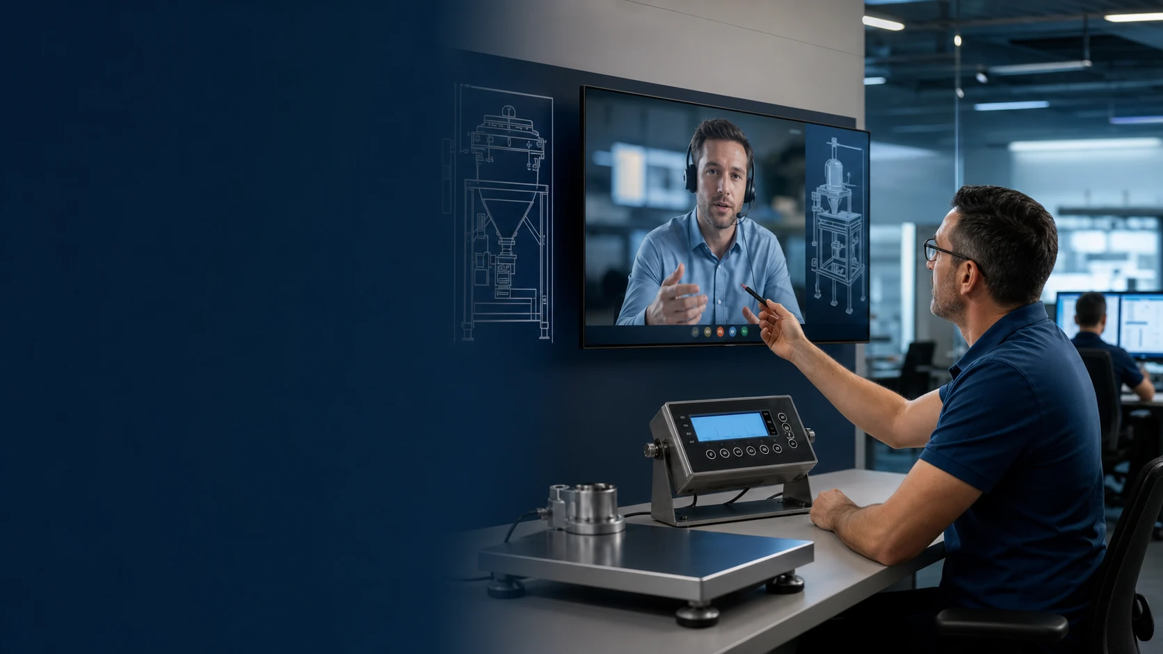
Forklift scale installation should begin with the exact truck, attachment chain, weighing architecture, operating task and jurisdiction—not with a generic kit. Release the work only after the responsible parties have confirmed safe modification, capacity information, mounting and cable routes, service access, commissioning tests and handover records for that configuration.
A scale kit can arrive at the workshop and still be impossible to fit responsibly. The data plate may describe a different carriage, the side-shifter may occupy the proposed sensor space, or the added geometry may require a new capacity review. Discovering any of these after the truck is out of service turns a documentation gap into downtime.
Begin with the exact truck, attachment chain, weighing architecture, operating task, and jurisdiction. Installation is ready to proceed when the responsible parties have evidence that the change preserves safe operation, required capacity information, service access, and a repeatable weighing procedure. Missing evidence belongs with the truck manufacturer or authorized dealer, scale supplier, site safety authority, or local metrology route—not on the workshop floor as an improvised decision.
The planning method below covers hydraulic sensing, carriage-mounted equipment, weighing forks, indicators, printers, and data connections. Actual fitting follows the truck and scale manufacturers’ current instructions and the site’s authorized energy-control procedure. Suitability for trade also depends on the complete configuration and jurisdiction; no family-level FMSCales description establishes that status for a named forklift.
Use five decisions to release the project
Ask “What evidence must exist before each stage is released?” before asking how many fitting hours to book. The five decisions below keep unresolved engineering questions visible while the supplier, dealer, installer, and buyer can still address them cheaply.
| Gate | Buyer’s release question | Minimum evidence |
|---|---|---|
| 1. Application freeze | Is the weighing task defined well enough to choose and test an architecture? | Load profile, operating cycle, record requirement, intended use, site conditions |
| 2. Truck compatibility and approval | May this exact truck and attachment configuration be modified or fitted as proposed? | Data plate, serial/model identity, attachment chain, dimensions, proposed drawings, written approvals where required |
| 3. Installation readiness | Can competent personnel perform the work with controlled energy, parts, access, and instructions? | Approved method, tools, isolation plan, component list, responsibilities, protected work area |
| 4. Commissioning | Does the installed system operate safely and produce acceptable results under the agreed test? | Inspection record, configuration backup, functional checks, reference method, repeatability and range results |
| 5. Handover | Can operators and maintainers use, inspect, verify, and escalate the system correctly? | As-built file, markings, training, daily checks, service plan, calibration/verification schedule |
Skipping a gate does not save time; it moves uncertainty into a more expensive stage. A missing fork dimension becomes a fitting delay. An undefined lift cycle becomes an “accuracy problem.” An unapproved attachment becomes a capacity and liability problem. An unspecified record becomes an integration change after commissioning.
Gate 1: freeze the operational decision
Write the use case in one sentence before discussing hardware:
The operator will obtain a weight during [defined handling step] so that [named role] can make [specific decision], and the accepted result will be recorded in [system or document].
A receiving check, internal load-control aid, inventory transaction, production issue, shipping declaration, and commercial sale are different applications. They may need different stability logic, identifiers, approvals, reference checks, and records. Do not allow “weigh pallets while moving them” to stand as the requirement.
Build a load profile using the real goods and handling units. Record minimum decision-relevant load, normal range, maximum planned load within the truck’s authorized limits, load centre, pallet or container geometry, uneven loads, attachments, number of lifts, floor condition, vibration, temperature, washdown, condensation, and electromagnetic environment. The weighing device never authorizes a load that the truck, attachment, forks, floor, rack, or procedure cannot safely handle.
Choose the acceptance event. For a fork- or carriage-based system, the load may need to be clear of contact, centered, stable, at a defined mast attitude, and held under specified motion conditions. A hydraulic system may use a controlled lift through a measurement window. These are examples, not universal instructions. The exact procedure comes from the selected system documentation and site validation.
Finally, decide whether the weight is advisory or controls a regulated transaction. OIML R 76-1:2006 covers non-automatic weighing instruments subject to official metrological control and defines such an instrument around operator intervention in accepting a result.[2] It does not make every forklift scale an approved instrument. The complete configuration, certificate scope, software, installation, use, and national rules determine the legal route.
Gate 2: identify the complete truck and attachment chain
“2.5-ton forklift” is not a compatibility file. Photograph and transcribe the manufacturer, model, serial or product identification, rated capacity, load centre, mast, maximum lift information, power system, tyre arrangement, and every relevant warning or attachment plate. Record the carriage class, fork dimensions, fork locking arrangement, side-shifter, fork positioner, rotator, clamps, extensions, quick-change devices, and any non-factory equipment.
The front-end chain matters because added mass, thickness, geometry, or load-centre change may affect residual capacity, visibility, clearance, and handling. In the United States, OSHA 29 CFR 1910.178 states that modifications or additions affecting capacity or safe operation require the manufacturer’s prior written approval and that capacity, operation, and maintenance plates or tags are changed accordingly. It also addresses identification and marking for non-factory front-end attachments.[1] Other jurisdictions have their own obligations; the buyer must obtain the applicable route rather than applying the U.S. rule globally.
Send the reviewer a package that can be checked without guessing:
- legible truck and attachment plates;
- fork length, width, thickness, spacing, taper, and locking details;
- carriage class and usable width;
- side and front photographs with the mast lowered and area safe;
- drawings of proposed brackets, sensors, indicator, printer, antennas, and cable paths;
- component masses and dimensional offsets;
- power connection and protection proposal;
- any hydraulic connection, pressure range, fittings, and contamination-control plan;
- required access for routine inspection and replacement;
- proposed calibration and test-load handling method.
Require a written response that identifies what has been reviewed and what remains conditional. A general brochure statement such as “fits most forklifts” is not approval for the named truck. If the truck maker or authorized route cannot confirm a modification that may affect safety or capacity, do not proceed on the basis of a scale seller’s verbal assurance.
Choose the installation route without mixing its risks
Different architectures place different demands on the truck. A hydraulic route may involve pressure sensors, transducers, position information, hoses or fittings, power, and an indicator. A carriage-mounted arrangement may add sensing structure and change the front-end geometry. Weighing forks replace or modify load-engaging components and introduce connectors, cables, batteries, or wireless nodes near frequent impact zones.
For each route, ask four separate questions:
- Mechanical: Where does load travel, what is added, what can contact the mast or load, and how will parts be retained and inspected?
- Hydraulic or sensor: Which circuit or sensing point is used, what pressure and temperature conditions apply, and how are leakage, contamination, overpressure, and service isolation controlled?
- Electrical: What voltage and transient range exists, where is overcurrent protection placed, what grounds or isolation are required, and how are moving cables protected?
- Operational: What exact movement creates an accepted weight, how is invalid motion shown, and what changes for attachments or unusual loads?
Do not splice into an arbitrary power lead or hydraulic point because it is convenient. Use the approved connection and protective method for the truck and selected system. Components mounted to a mast or carriage need clearance through the full authorized movement envelope. Check at safe, controlled conditions for chains, rollers, hoses, tilt, sideshift, fork movement, load backrest, cab guard, and visibility. No person should enter a crush zone or work beneath an unsupported raised assembly.
Gate 3: release work with an agreed installation package
The installer needs the current truck manual, scale installation instructions, approved drawings, parts list, torque or fitting requirements supplied by the responsible manufacturers, and a site-specific safe-work method. Only trained and authorized personnel should isolate, modify, reconnect, and test the equipment. OSHA requires unsafe powered industrial trucks to be removed from service and repairs to be made by authorized personnel; that is a useful stop-work principle even where another jurisdiction governs.[1]
Before work starts, hold a short release review:
- Is the truck positively identified and in safe condition?
- Are the selected scale components and versions the ones reviewed?
- Are energy isolation and stored-energy controls defined?
- Is the work area separated from normal traffic?
- Are lifting or support devices rated and inspected for the task?
- Are approved fittings, cables, glands, fuses, fasteners, guards, and protective materials available?
- Are hydraulic cleanliness and spill controls ready if relevant?
- Is the rollback plan defined if a component or dimension does not match?
- Who may approve a deviation from the drawing?
Any unexplained interference, structural damage, hydraulic leak, damaged wiring, missing approval, altered safety device, or mismatch between the truck and documentation is a stop-work condition. Record the condition, secure the equipment, and escalate. Do not drill, weld, grind, add counterweight, alter forks, defeat a guard, or change a safety setting as an improvised solution.
Protect the signal chain from the real warehouse
An installation can pass a static demonstration and fail within weeks if connectors, hoses, or cables sit in impact, pinch, flex, heat, moisture, or washdown zones. Trace the full signal chain while the truck is safely taken through its authorized motions. Look for minimum bend radius, abrasion, mast transitions, strain relief, connector orientation, water paths, sharp edges, moving chains, tyre spray, battery access, tilt-cylinder movement, and places where operators climb or store objects.
Mount the indicator where the operator can read required status without losing necessary visibility or striking the unit during entry. Avoid sharp projections, blocked controls, interference with protective structures, and awkward reaches. If operators enter IDs or tare values, test the interaction with the actual PPE, lighting, gloves, language, and task time used on site.
Record every connector, cable, hose, fuse, sensor, bracket, seal, and software component by identifier where available. Photograph protected routes before covers are closed. This as-built evidence becomes invaluable when a replacement truck, attachment, sensor, or workshop repair changes the behavior months later.
Gate 4: commission safety and measurement as separate workstreams
Commissioning is not complete when the display turns on. First perform the truck and installation checks required by the responsible manufacturers and site procedure. Confirm guards, retention, markings, leaks, cable clearance, control function, visibility, and that no fault or modification remains unresolved. If the truck is unsafe, take it out of service; do not use a weight test to justify continued operation.
Then commission the measurement under an approved test plan. NIST Handbook 44’s 2026 Scales Code includes installation and use requirements for scales used in its U.S. legal-metrology context, while OIML R 76 provides an international recommendation framework.[2][3] Neither source is a substitute for the exact product manual or local authority. For an internal process installation, they still illustrate why support, environment, indication, eccentric loading, repeatability, and controlled test conditions matter.
The buyer’s test plan should define:
- reference loads and their traceability or documented suitability;
- test range covering light, normal, and high operational points;
- load geometry and load centre;
- mast, fork, tilt, height, and movement conditions;
- warm-up and zero procedure from the actual manual;
- number and order of repetitions;
- acceptance calculation agreed before testing;
- behavior during unstable motion, overload indication, lost sensor, low battery, or communications loss;
- comparison of displayed, printed, and transmitted values;
- user roles and protection of configuration or calibration access.
Do not adjust after every inconvenient result. Investigate whether the load moved, the forks contacted another surface, the lift cycle changed, the reference was unsuitable, or the installation is mechanically unstable. Calibration changes the relationship between indication and reference; it cannot repair unsafe hardware or inconsistent operation.
Create a record that survives a service visit
At handover, the buyer needs a serviceable project file as well as an operator demonstration. Include the approved equipment identities, truck and attachment configuration, drawings, parts and firmware versions, installation photographs, power and sensor routes, parameter backup, calibration and verification records, test-load information, acceptance results, operator instructions, fault actions, service contacts, and change-control rules.
Define events that require inspection or re-verification: fork or attachment replacement, mast or hydraulic repair, sensor or indicator replacement, cable damage, collision, overload, firmware update, configuration restoration, movement to another truck, prolonged storage, or unexplained drift. Specify who may restore the system after each event.
Training should use real tasks and exceptions. Each operator should demonstrate the correct weighing movement, zero and tare rules, load identification, invalid-reading response, record correction, and stop-work escalation. Maintenance staff need protected access, inspection points, backup/restore controls, and a rule against changing calibration to hide a mechanical problem.
Buyer’s final installation acceptance checklist
Do not sign the installation acceptance until the following statements can be supported:
- The exact truck, attachment chain, and scale configuration are identified.
- Required modification and capacity approvals or markings are complete.
- The installation matches controlled drawings, with deviations approved and recorded.
- No bracket, sensor, hose, cable, indicator, or connector creates interference or an unprotected damage path.
- Required guards, plates, warnings, and truck functions are present and legible.
- The truck has passed the responsible safety and operational checks.
- The measurement test covers representative loads, positions, and operator conditions.
- Reference equipment and results are recorded, not described only as “passed.”
- Invalid states and power, signal, printer, or network failures produce the agreed safe response.
- Operators and maintainers have demonstrated the procedures relevant to their roles.
- As-built, configuration, calibration, training, and service records have named owners.
- Regulated use, if intended, has been confirmed for the complete instrument and jurisdiction.
When to stop and escalate
Stop the installation or remove the truck from service if approval is missing; a modification may affect safe operation or capacity; a plate is absent or inconsistent; a fork, carriage, mast, hose, sensor, cable, connector, guard, or bracket is damaged; there is a hydraulic leak; parts interfere through the movement range; an unsafe fault remains; the test load cannot be handled under a controlled plan; or the installed result is unstable for reasons the team cannot explain.
Escalate to the truck manufacturer or authorized dealer for truck and attachment questions, to the scale supplier for exact installation and configuration questions, to competent lifting/hydraulic/electrical personnel for their work, to the site EHS authority for the safe method, and to the competent metrology authority for regulated-use decisions. A successful weight display is not evidence that all five responsibilities have been met.
Prepare a reviewable installation request
For a model-level review, send FMSCales the forklift make, model, serial series, complete data plates, attachment list, carriage and fork dimensions, typical and maximum loads, load centre, operating cycle, site conditions, power information, required record, intended legal use, and clear photographs of the proposed routes. The useful output is a written list of confirmed points, exclusions, required approvals, unresolved decisions, and proposed commissioning evidence. A generic promise that a kit “fits most trucks” cannot replace that review.
Freeze the approved truck configuration before installation
Installation starts with the exact truck, data plate, carriage, forks, load centre and attachments. Any mechanical, hydraulic or electrical change must follow the truck and weighing-system instructions, preserve safe operation and end with a documented acceptance test.
- Record the truck and attachment configuration before work begins
- Route sensors, cables and connectors away from pinch, abrasion and heat risks
- Protect power and communication interfaces and document isolation points
- Verify the defined lift procedure with representative reference loads
Buyer-task questions
Can a scale be moved to a different forklift without review?
Do not assume so. Truck geometry, carriage, forks, attachments, hydraulics, power and residual capacity can change the installation and calibration.
What belongs in the installation handover?
Record the configured truck and attachments, wiring or hydraulic changes, settings backup, operating procedure, acceptance results, user training and service responsibilities.
References
The following official and first-party sources support the bounded examples, standards context and evaluation methods used in this guide. They do not verify an FMSCales configuration.
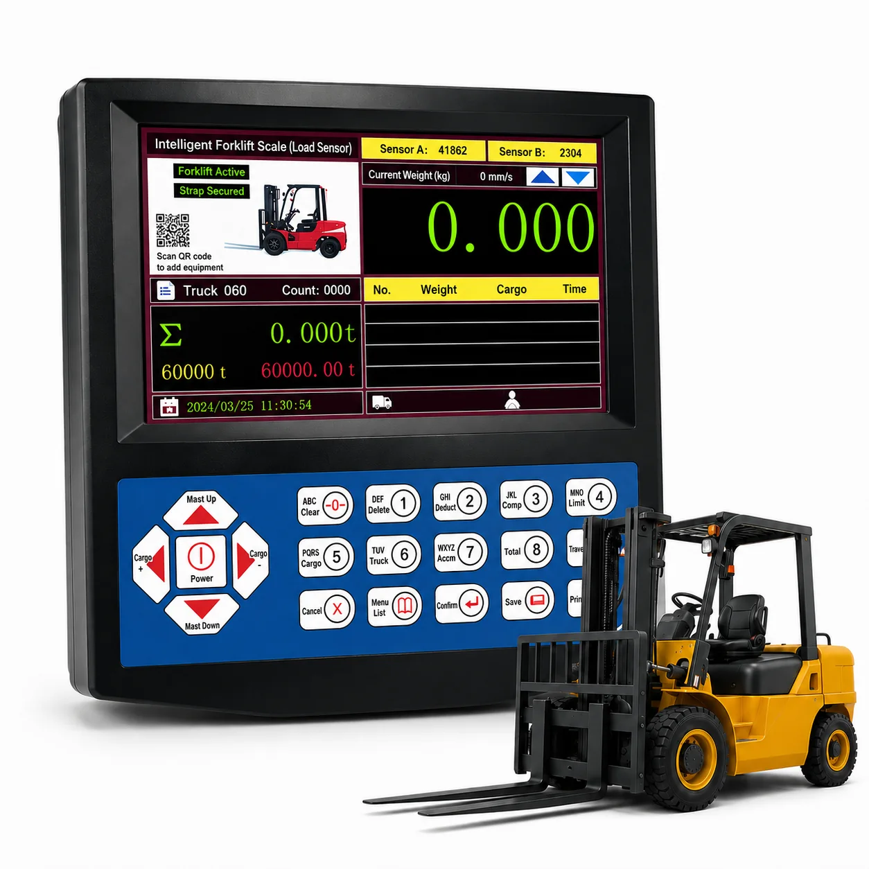 Forklift Scales
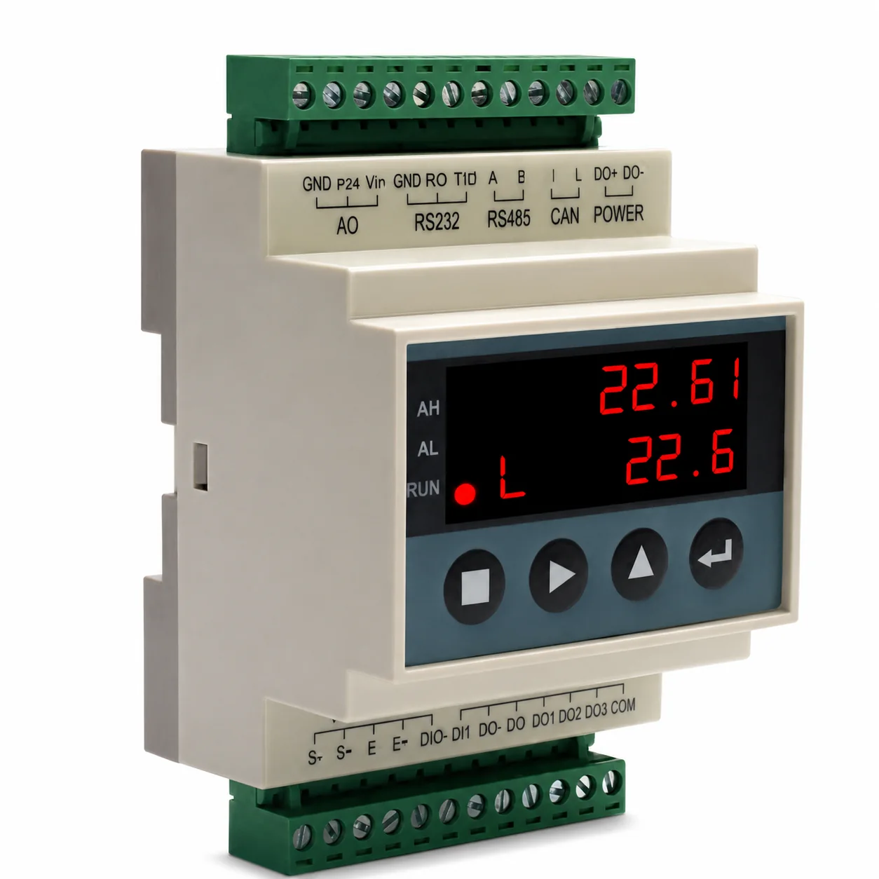 Weighing Indicators
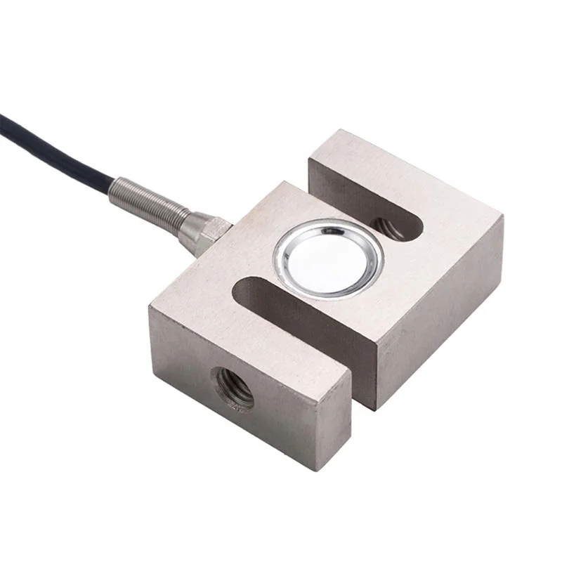 Load Cells
 Load Cell Accessories