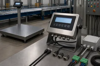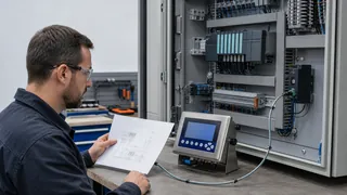
A weighing indicator presents a weight result and may add local functions. A transmitter converts the measurement into an industrial output for another system. A controller uses the measurement in defined control logic, while a weighing module is usually an integration component inside a larger machine or cabinet. Product names vary, so the final role must be confirmed from the exact model manual, I/O list and tested data path.
1. A weighing indicator vs transmitter decision starts with the signal destination
Begin with one measurement event and trace where it must go. If an operator needs to see, zero, tare or accept the result locally, an indicator role is present. If another control or information system only needs a conditioned weight value or status, a transmitter role may be sufficient. A device can combine both roles, but the proposal should identify them separately.
The comparison must use the exact manual and firmware revision. Terms used by different manufacturers are not guaranteed to describe the same input circuits, filtering, stability logic, outputs or user controls.
| Role | Primary responsibility | Evidence to request |
|---|---|---|
| Indicator | Present and manage a local weighing result | Display functions, keys, units, stability logic and user permissions |
| Transmitter | Deliver a measurement and status to another system | Signal type, protocol role, register map, scaling, update rate and fault states |
| Controller | Use weight in a defined control sequence | Setpoints, output logic, interlocks, timing, manual mode and safe failure behaviour |
| Module | Embed weighing measurement in a machine or cabinet | Mechanical format, power, host interface, service method and integration responsibility |
2. A weighing controller vs indicator comparison depends on who makes the process decision
An indicator can display a stable value and may provide relays or setpoints, but that does not automatically make it the owner of a batching, filling or interlock sequence. A controller role begins when the device is responsible for defined process actions, state transitions, limits and exception handling.
Write a state table before ordering. Include ready, zeroing, filling, stable, accepted, overload, sensor fault, communication loss, manual intervention and restart. Assign each transition to the weighing device, PLC or supervisory system so two devices do not issue conflicting commands.
- Identify every output and the equipment it can energise.
- Define permissives and interlocks outside the normal weight sequence.
- State what happens after a power cycle or invalid measurement.
- Require a controlled test for automatic and manual modes.
3. Treat the load cells, electronics and software as one measurement chain
The device cannot be selected independently of the load-cell signal, excitation, cable arrangement, junction hardware, dead load and required measurement range. Confirm the number and type of connected sensors, signal level, connection method, environmental conditions and any intrinsic-safety boundary before comparing electronics.
A component classification or resolution value does not establish installed system performance. The complete structure, load path, wiring, configuration and operating procedure must be verified with a suitable reference under defined conditions.
4. Request interface evidence instead of relying on a protocol label
A Modbus or Ethernet claim does not define the weighing record. Request the exact register or message map, device role, addresses, data types, byte and word order, units, scaling, status bits, write permissions and firmware revision. For event records, also define identifiers, timestamps, acknowledgement, retry and duplicate handling.
OPC UA can provide a richer information model, but the buyer still needs the vendor namespace, security configuration, update behaviour and application semantics. Connectivity is not acceptance until the required normal, invalid and recovery cases have been tested.
| Data need | Minimum acceptance question |
|---|---|
| Live weight | How are units, decimal position, stability and invalid states represented? |
| Completed record | What creates the record, gives it a unique ID and confirms storage? |
| Control value | Which system validates the value before acting on it? |
| Diagnostics | How are sensor, overload, configuration and communication faults distinguished? |
5. Use a five-step selection workflow
First, define the operational decision. Second, identify the measurement chain. Third, assign display, transmission, control and record ownership. Fourth, map the interfaces and failure states. Fifth, compare exact models against a written acceptance test.
This workflow prevents a buyer from purchasing a capable device that still fails the project because it lacks the required operator controls, record semantics, electrical interface or recovery behaviour.
- Sample screen or operator sequence
- Load-cell and power schedule
- I/O and protocol matrix
- Normal, fault and restart state table
- Model-specific document and acceptance checklist
6. Keep legal use and performance claims model-specific
Do not infer legal-for-trade eligibility from a generic indicator, transmitter or module label. Confirm the complete instrument, certificate scope, software, connected load cells, installation, intended use and jurisdiction with the responsible authority or verification route.
Likewise, do not compare devices from display divisions or converter resolution alone. State the required operating range, environmental and loading conditions, reference method, number of tests and acceptance limit for the complete system.
Decision guidance
Choose the device from the measurement owner, required operator interaction, control boundary, record destination and failure behaviour. Do not infer a role from the enclosure or marketing name alone.
The role names are not universal model classifications. A port, protocol logo or generic product label does not prove register compatibility, control capability, legal-for-trade status or suitability for a specific machine.
Frequently asked questions
Can one device be an indicator and a controller?
Yes, one model may combine a display, measurement processing, setpoints and control outputs. Confirm which functions are enabled in the quoted hardware and firmware, then test each required state and output.
Does RS-485 make a weighing device a transmitter?
No. RS-485 describes an electrical communication layer. The protocol role, register map, units, status values, update behaviour and permissions still depend on the exact device.
Is a weighing module always installed without a display?
No. Some modules are designed mainly for cabinet or machine integration, while others may support a local display or service interface. Confirm the supplied components and operating workflow.
Which device should own the final weight record?
Assign ownership from the business workflow. A local indicator may own an accepted transaction, or it may provide a measurement to a PLC, WMS or ERP that owns the completed record.
References
The following official and first-party sources support the bounded examples, standards context and evaluation methods used in this guide. They do not verify an FMSCales configuration.
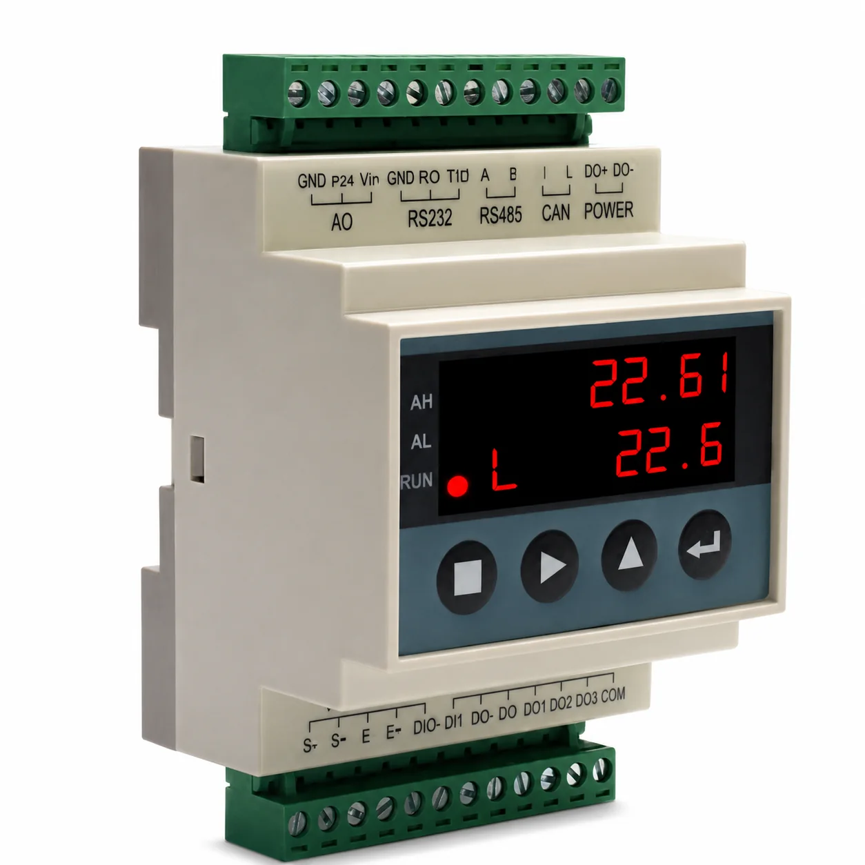 Weighing Indicators
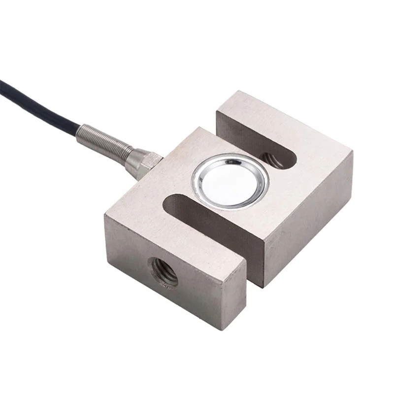 Load Cells
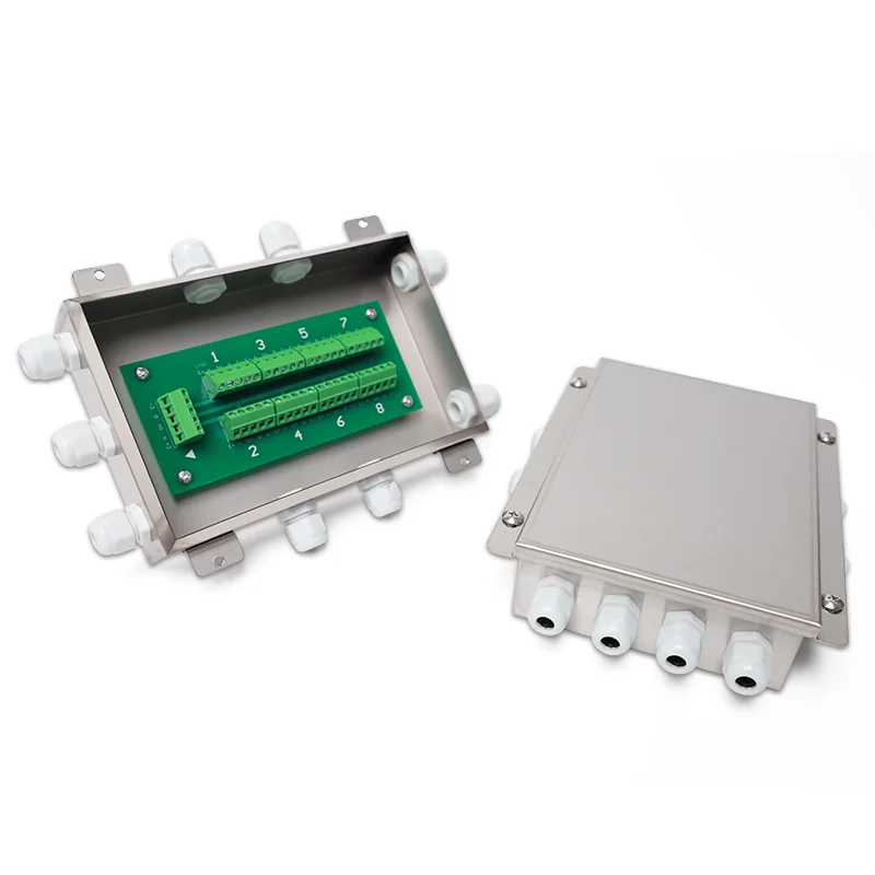 Load Cell Accessories